
A Music Reactive Light (also called a Sound Reactive Light or Music Sync Light) is a lighting system that changes its colors, brightness, or patterns according to the music or sound being played.
Components Required:
- CD4017 IC
- 9014 Transistor
- Resistor – 20k, 470k,2Mohm
- Micrpphone
- Capacitor – 1uf, 100uf
- Multicolor LED
Special Thanks to Our Sponser – JLCPCB:
No project is complete without the right tool and materials. That’s why our sponser JLCPCB stepped into provide essential material for the project. JLCPCB is a leading provider of high quality printed circuit board and PCB assembling services.
Simply head over to JLCPCB, Upload your gerber file, select specification and just place your order.
48-Hour Turnaround for 6 Layer PCBs!

$0 for 2u” ENIG. Free Via-in-Pad. High Precision. Sign Up to Get $80 New User Coupons.

How To Order PCB
CD4017 IC (Decade Counter / Johnson Counter)
The CD4017 is a CMOS Decade Counter IC with 10 decoded outputs (Q0–Q9). It advances one output HIGH for every clock pulse, making it one of the most popular ICs for LED chasers, sequence controllers, and timing circuits.
Key Features
- IC Type: CMOS Decade Counter
- Package: DIP-16 / SOIC-16
- Operating Voltage: 3V to 15V (up to 18V max absolute)
- 10 Decoded Outputs: Q0 to Q9
- One output HIGH at a time
- Clock Enable and Reset pins
- Carry Out pin for cascading multiple CD4017 ICs
- Low power consumption
Pin Configuration
| Pin | Function |
|---|---|
| 1 | Q5 |
| 2 | Q1 |
| 3 | Q0 |
| 4 | Q2 |
| 5 | Q6 |
| 6 | Q7 |
| 7 | Q3 |
| 8 | GND |
| 9 | Q8 |
| 10 | Q4 |
| 11 | Q9 |
| 12 | Carry Out (CO) |
| 13 | Clock Enable (Active LOW) |
| 14 | Clock Input |
| 15 | Reset (Active HIGH) |
| 16 | VCC (3–15V) |
How It Works
- On power-up, Q0 is HIGH.
- Every rising edge on the Clock (Pin 14) shifts the HIGH output:
- 1st pulse → Q1
- 2nd pulse → Q2
- …
- 10th pulse → Back to Q0
- Reset (Pin 15) immediately returns the counter to Q0.
- Clock Enable (Pin 13) must be LOW for counting; HIGH pauses the count.
Common Applications
- LED Chaser / Running Lights
- Traffic Light Controller
- Dice Circuits
- Sequential Switching
- Robotics
- Automatic Water Level Indicators
- Event Counters
- Digital Timers (with NE555)
- Frequency Divider (÷10)
Typical Connection with NE555
- NE555 Output → Pin 14 (Clock)
- Pin 13 → GND
- Pin 15 → GND (or push button for reset)
- Pin 16 → +5V to +12V
- Pin 8 → GND
- LEDs connected to Q0–Q9 through 220Ω–1kΩ resistors.
This combination creates the classic 10-LED running light (Knight Rider/LED Chaser) circuit.
S9014 (9014) Transistor
The S9014 is a general-purpose NPN bipolar junction transistor (BJT) commonly used for low-power switching and signal amplification in electronic circuits.
Key Features
- Transistor Type: NPN
- Package: TO-92
- Maximum Collector-Emitter Voltage (VCEO): 45V
- Maximum Collector Current (IC): 100mA
- Power Dissipation: 400mW (typical)
- DC Current Gain (hFE): 100–1000 (depends on grade and operating conditions)
- Operating Frequency (fT): Approximately 100–150MHz
Pin Configuration
With the flat side facing you and leads pointing downward:
| Pin | Function |
|---|---|
| 1 | Emitter (E) |
| 2 | Base (B) |
| 3 | Collector (C) |
Note: Some manufacturers may use a different pin arrangement. Always verify the pinout from the specific datasheet before soldering.
Applications
- LED switching
- Relay driving (with a flyback diode)
- Audio pre-amplifiers
- Signal amplification
- Sensor interface circuits
- Microcontroller output switching (Arduino, ESP32, etc.)
- Small DC motor control (within current limits)
Typical Specifications
| Parameter | Value |
|---|---|
| Type | NPN |
| VCEO | 45V |
| IC (Max) | 100mA |
| hFE | 100–1000 |
| Package | TO-92 |
Common Equivalent Transistors
- BC547
- BC548
- 2N3904
- PN2222A / 2N2222 (with attention to pinout and ratings)
- S8050 (higher current, but different characteristics)
Typical Use with Arduino
- Emitter → GND
- Collector → Negative side of LED/Relay/Buzzer
- Base → Arduino GPIO through a 1kΩ–4.7kΩ resistor
- Load positive terminal → +5V
The transistor acts as an electronic switch, allowing a low-current Arduino pin to control a higher-current load.
More Projects
-

Building an Automatic Dark Sensor with BD139 Transistor
Light and darkness are two sides of the same coin, influencing our daily lives in ways we often overlook. Imagine a world where lights adjust themselves according to the ambient light—a realm where darkness triggers illumination automatically. Such a world isn’t far-fetched, and with the BD139 transistor, creating an automatic dark sensor becomes an exciting…
-

Servo Motor Controller Circuit
A servo motor controller circuit is an electronic system designed to control the position, speed, and direction of a servo motor. Servo motors are used in various applications, including robotics, automation, and precision control systems. The controller circuit typically receives control signals (often from a microcontroller or external controller) and adjusts the servo motor’s movement…
-
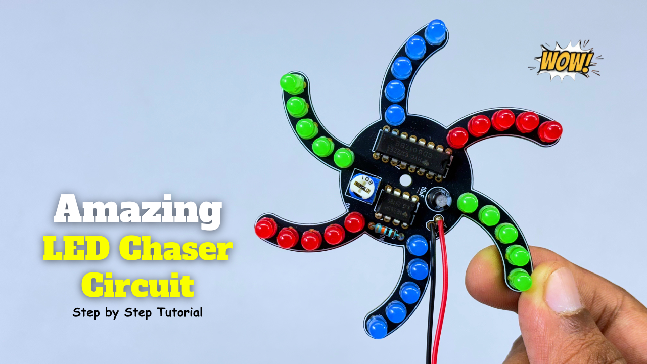
Amazing LED Chaser Circuit – Beautiful Decoration Idea
An LED chaser is an electronic circuit that lights LEDs one after another in a sequence. It creates a running or chasing light effect commonly seen in decorations and indicators. The sequence can move left-to-right, right-to-left, or in patterns. It’s usually built using ICs like 555 timer + 4017 decade counter. Components Required: Circuit Diagram:…