
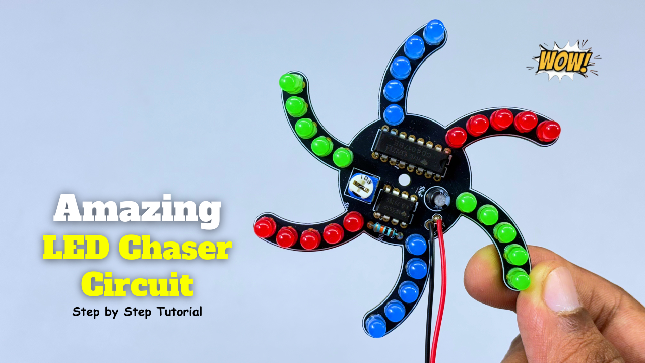
LED chasers are a fun and creative way to display a sequence of lights. In this blog post, we’ll show you how to build an LED chaser using a 555 timer and CD4017 decade counter.
Building an LED chaser with a 555 timer and CD4017 is a fun and educational project. It demonstrates the principles of digital electronics and sequential logic. With this circuit, you can create a mesmerizing display of lights that will impress your friends and family.
Components Required:
- 555 Timer IC
- CD4017 IC
- Red LED
- Yellow LED
- 9013 Transistor
- 1k Ohm Resistor
- 220 ohm Resistor
Special Thanks to Our Sponser – JLCPCB:
No project is complete without the right tool and materials. That’s why our sponser JLCPCB stepped into provide essential material for the project. JLCPCB is a leading provider of high quality printed circuit board and PCB assembling services.
Simply head over to JLCPCB, Upload your gerber file, select specification and just place your order.
48-Hour Turnaround for 6 Layer PCBs!

$0 for 2u” ENIG. Free Via-in-Pad. High Precision. Sign Up to Get $80 New User Coupons.

How To Order PCB
555 Timer IC
The 555 timer IC is a legendary integrated circuit that has been a cornerstone of electronics projects for decades. Introduced in 1972 by Signetics, this versatile chip has become a staple in the world of electronics, renowned for its simplicity, reliability, and flexibility. The 555 timer IC is a monolithic timing circuit that can be used in a wide range of applications, including oscillators, timers, pulse generators, and alarm circuits. It consists of two main components: a voltage-controlled oscillator (VCO) and a flip-flop. The VCO generates a square wave output, while the flip-flop acts as a Schmitt trigger, providing hysteresis and ensuring clean switching.
Pinout and Configuration
The 555 timer IC has eight pins, each with a specific function:
- Pin 1: Ground
- Pin 2: Trigger input
- Pin 3: Output
- Pin 4: Reset input
- Pin 5: Control voltage input
- Pin 6: Threshold input
- Pin 7: Discharge pin
- Pin 8: Supply voltage (Vcc)
The 555 can be configured in various modes, including:
- Monostable (one-shot) mode
- Astable (free-running) mode
- Bistable (Schmitt trigger) mode
Applications and Projects
The 555 timer IC has been used in countless projects, including:
- Timer circuits (e.g., egg timers, alarm systems)
- Oscillators (e.g., audio signals, LED flashers)
- Pulse generators (e.g., infrared transmitters, ultrasonic cleaners)
- Alarm circuits (e.g., motion detectors, smoke detectors)
- LED flashers and blinkers
- Audio circuits (e.g., tone generators, sound effects)
CD4017 IC
CD4017 IC: A Decade Counter for Your Electronics Projects
The CD4017 IC is a decade counter chip that has been widely used in electronic projects for decades. It’s a versatile and reliable component that can be used in a variety of applications, from simple counters to complex digital displays.
It is a decade counter chip that counts from 0 to 9. It has 10 output pins, each representing a digit from 0 to 9. The chip also has a carry pin that can be used to connect multiple CD4017 chips together to create a larger counter.
Pinout and Configuration
The CD4017 IC has 16 pins, including:
- 10 output pins (Q0-Q9)
- 1 carry pin (CARRY)
- 1 reset pin (RESET)
- 1 clock pin (CLOCK)
- 1 input pin (INPUT)
- 2 power pins (VCC and GND)
How it Works
The CD4017 IC works by incrementing the count each time a clock pulse is applied to the clock pin. The count can be reset to 0 by applying a reset pulse to the reset pin. The carry pin can be used to connect multiple CD4017 chips together to create a larger counter.
Applications and Projects
The CD4017 IC has been used in a wide range of applications, including:
- Digital clocks
- Counters
- Display drivers
- Sequencers
- Traffic lights
- Scoreboards
9013 – Transistor
The 9013 (S9013/SS9013) is a general-purpose NPN silicon transistor commonly used for switching and low-power amplification. It is widely found in DIY electronics, Arduino projects, toys, and audio circuits.
Specifications
- Type: NPN Bipolar Junction Transistor (BJT)
- Package: TO-92
- Collector-Emitter Voltage (VCEO): 20–30 V (depends on manufacturer)
- Collector Current (IC): 500 mA (Max)
- Power Dissipation: 625 mW
- Transition Frequency (fT): Up to 100–140 MHz
- DC Gain (hFE): 64–202 (varies by gain group)
Applications
- Relay driver circuits
- LED switching
- Motor driver circuits
- Audio amplifier stages
- Arduino and microcontroller interfacing
- General-purpose switching
Complementary Transistor
- PNP Equivalent: 9012 (S9012)
More Projects
-

Building an Automatic Dark Sensor with BD139 Transistor
Light and darkness are two sides of the same coin, influencing our daily lives in ways we often overlook. Imagine a world where lights adjust themselves according to the ambient light—a realm where darkness triggers illumination automatically. Such a world isn’t far-fetched, and with the BD139 transistor, creating an automatic dark sensor becomes an exciting…
-

Servo Motor Controller Circuit
A servo motor controller circuit is an electronic system designed to control the position, speed, and direction of a servo motor. Servo motors are used in various applications, including robotics, automation, and precision control systems. The controller circuit typically receives control signals (often from a microcontroller or external controller) and adjusts the servo motor’s movement…
-
Amazing LED Chaser Circuit – Beautiful Decoration Idea
An LED chaser is an electronic circuit that lights LEDs one after another in a sequence. It creates a running or chasing light effect commonly seen in decorations and indicators. The sequence can move left-to-right, right-to-left, or in patterns. It’s usually built using ICs like 555 timer + 4017 decade counter. Components Required: Circuit Diagram:…