
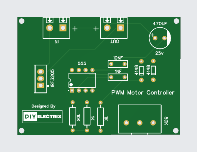
A Dimmer is an electronic device that uses PWM signals to control the speed and direction of a motor. It works by varying the width of the pulses to adjust the average voltage applied to the motor, thereby controlling its speed.
Components Used:
- 9014 Transistor
- 510 Ohm
- 33k Ohm
- Red LED * 5
- Green LED * 5
- 22uf Capacitor
- Connector
- 3.7v Battery
Gerber File:
Special Thanks to Our Sponser – JLCPCB:
No project is complete without the right tool and materials. That’s why our sponser JLCPCB stepped into provide essential material for the project. JLCPCB is a leading provider of high quality printed circuit board and PCB assembling services.
Simply head over to JLCPCB, Upload your gerber file, select specification and just place your order.
48-Hour Turnaround for 6 Layer PCBs!

Discover Easy, Affordable, and Reliable PCB manufacturing with JLCPCB! Register to get $60 New customer coupons.

How To Order PCB
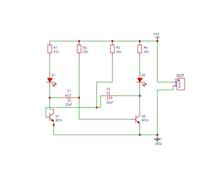
Circuit Diagram:
9014 Transistor:
The 9014 is a low-power, general-purpose NPN transistor used in many small signal and low-voltage applications. It is designed for amplifying or switching electronic signals. Due to its low cost and easy availability, it’s a favorite among hobbyists and engineers alike.
🔍 Technical Specifications
| Parameter | Value |
|---|---|
| Type | NPN |
| Collector-Emitter Voltage (Vce) | 45V |
| Collector-Base Voltage (Vcb) | 50V |
| Emitter-Base Voltage (Veb) | 5V |
| Collector Current (Ic) | 800mA |
| Power Dissipation | 625mW |
| DC Current Gain (hFE) | 64–400 |
| Transition Frequency (fT) | 250 MHz |
| Package Type | TO-92 |
9014 Transistor
The 9014 transistor comes in a TO-92 package, which has three terminals:
E (Emitter) – Current flows out from here.
B (Base) – Controls the transistor.
C (Collector) – Current flows into this terminal.
Modes of operation:
Cut-off Region (OFF): No base current → No collector current.
Active Region (Amplifier): Small base current → Proportional collector current.
Saturation Region (ON/Switching): Base current high → Maximum collector current.
More Projects
-
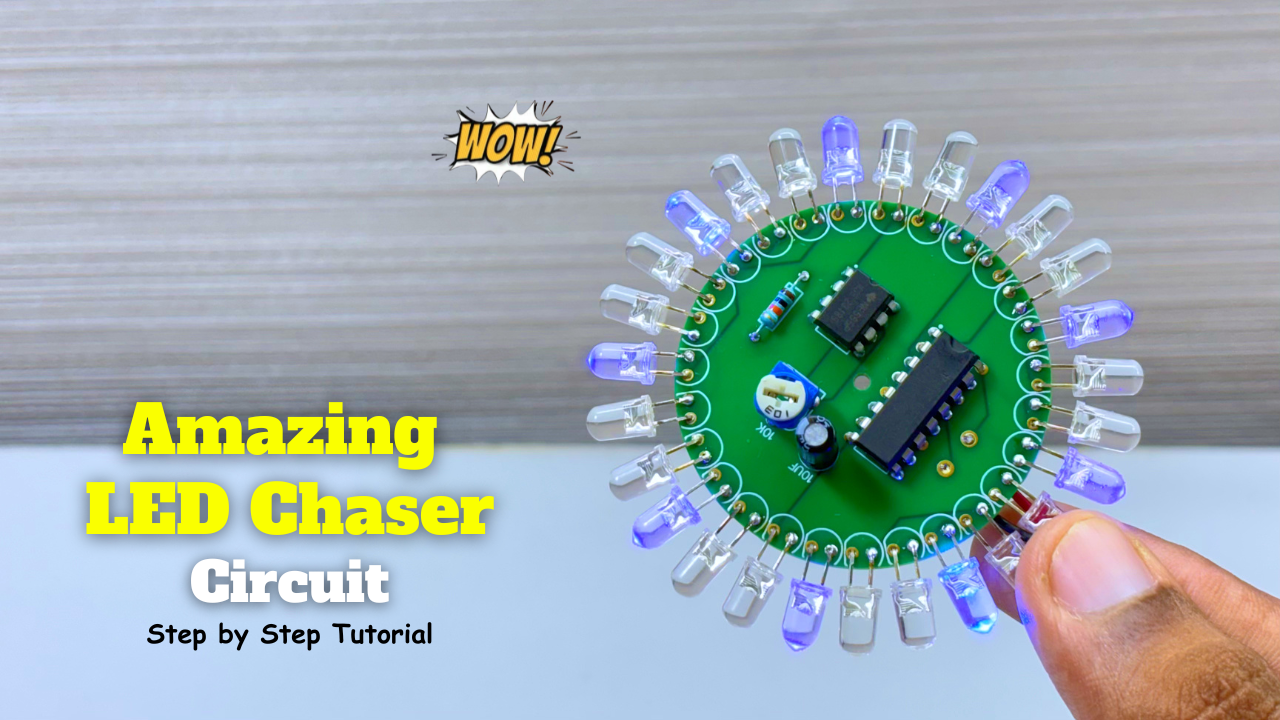
Amazing LED Chaser Circuit – Beautiful Decoration Idea
LED chasers are a fun and creative way to display a sequence of lights. In this blog post, we’ll show you how to build an LED chaser using a 555 …
-
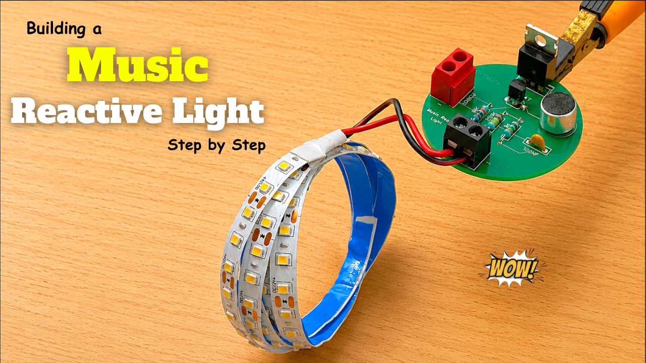
Music Reactive Light Circuit
A Music Reactive Light (also called a Sound Reactive Light or Music Sync Light) is a lighting system that changes its colors, brightness, or patterns according to the music or …
-
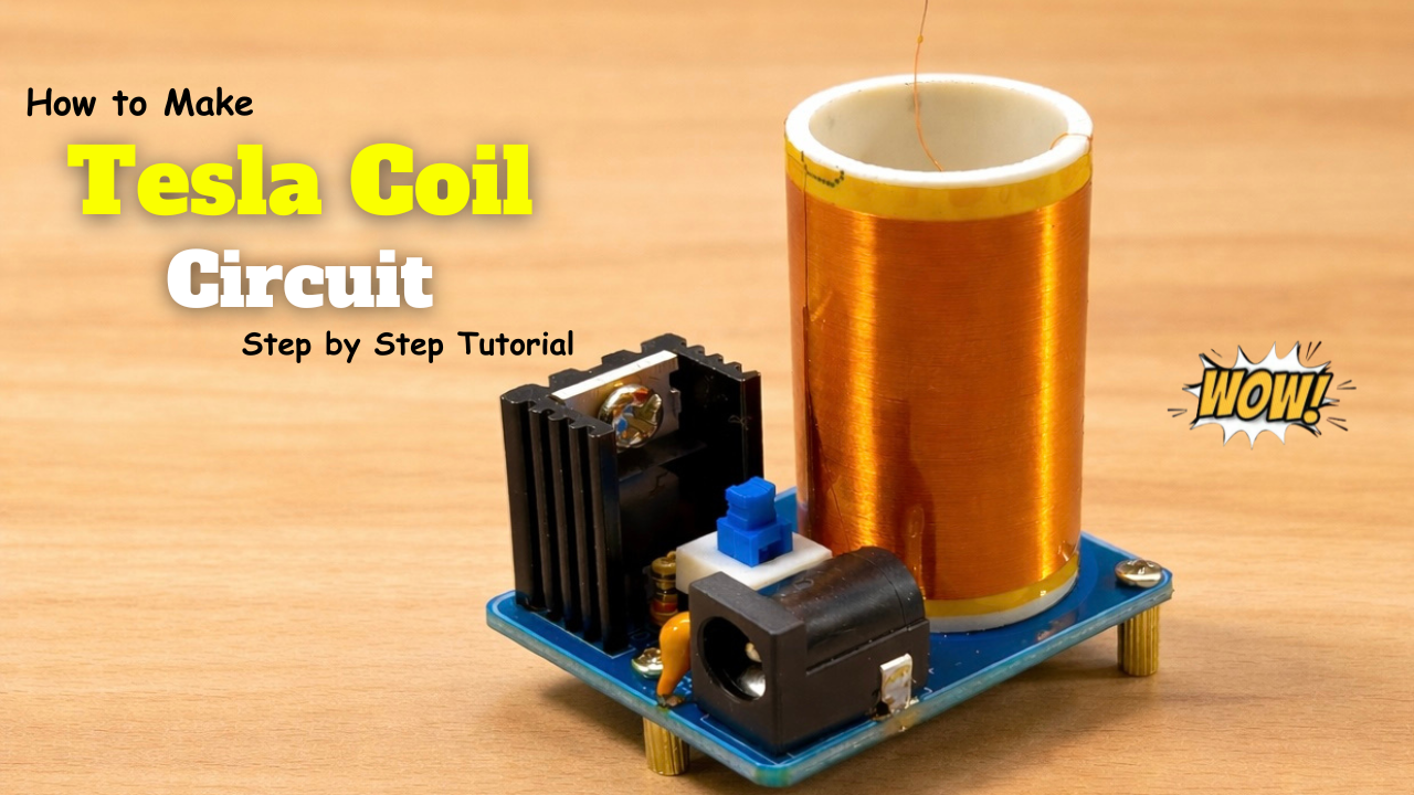
Mini Tesla Coil
A Tesla coil is an electrical device invented by Nikola Tesla in 1891. It is designed to generate very high voltage, low current, high-frequency electricity. In simple terms, it’s a …