
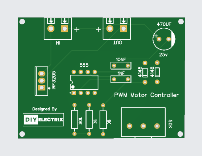
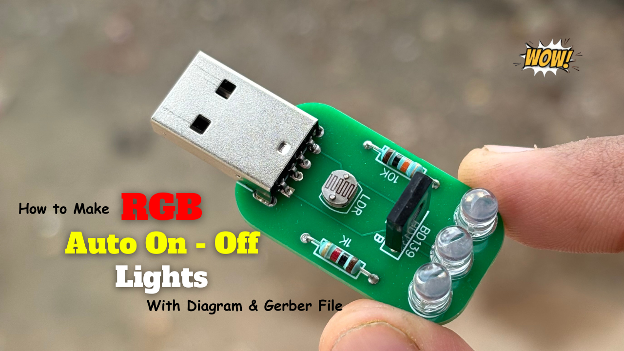
A Dimmer is an electronic device that uses PWM signals to control the speed and direction of a motor. It works by varying the width of the pulses to adjust the average voltage applied to the motor, thereby controlling its speed.
Components Used:
- 9014 Transistor
- 510 Ohm
- 33k Ohm
- Red LED * 5
- Green LED * 5
- 22uf Capacitor
- Connector
- 3.7v Battery
Gerber File:
Special Thanks to Our Sponser – JLCPCB:
No project is complete without the right tool and materials. That’s why our sponser JLCPCB stepped into provide essential material for the project. JLCPCB is a leading provider of high quality printed circuit board and PCB assembling services.
Simply head over to JLCPCB, Upload your gerber file, select specification and just place your order.
48-Hour Turnaround for 6 Layer PCBs!

Discover Easy, Affordable, and Reliable PCB manufacturing with JLCPCB! Register to get $60 New customer coupons.

How To Order PCB
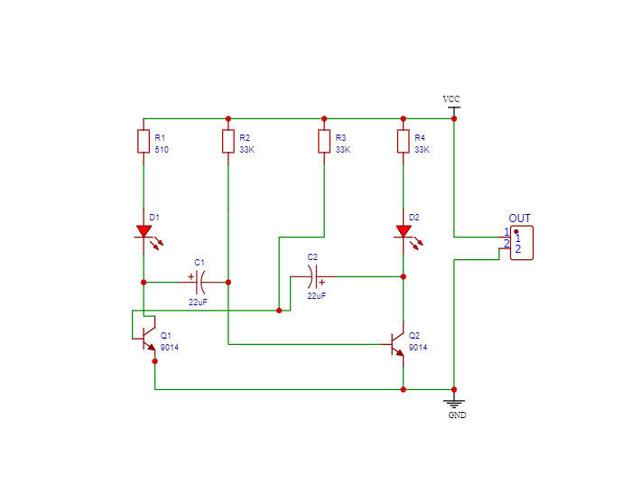
Circuit Diagram:
9014 Transistor:
The 9014 is a low-power, general-purpose NPN transistor used in many small signal and low-voltage applications. It is designed for amplifying or switching electronic signals. Due to its low cost and easy availability, it’s a favorite among hobbyists and engineers alike.
🔍 Technical Specifications
| Parameter | Value |
|---|---|
| Type | NPN |
| Collector-Emitter Voltage (Vce) | 45V |
| Collector-Base Voltage (Vcb) | 50V |
| Emitter-Base Voltage (Veb) | 5V |
| Collector Current (Ic) | 800mA |
| Power Dissipation | 625mW |
| DC Current Gain (hFE) | 64–400 |
| Transition Frequency (fT) | 250 MHz |
| Package Type | TO-92 |
9014 Transistor
The 9014 transistor comes in a TO-92 package, which has three terminals:
E (Emitter) – Current flows out from here.
B (Base) – Controls the transistor.
C (Collector) – Current flows into this terminal.
Modes of operation:
Cut-off Region (OFF): No base current → No collector current.
Active Region (Amplifier): Small base current → Proportional collector current.
Saturation Region (ON/Switching): Base current high → Maximum collector current.
More Projects
-
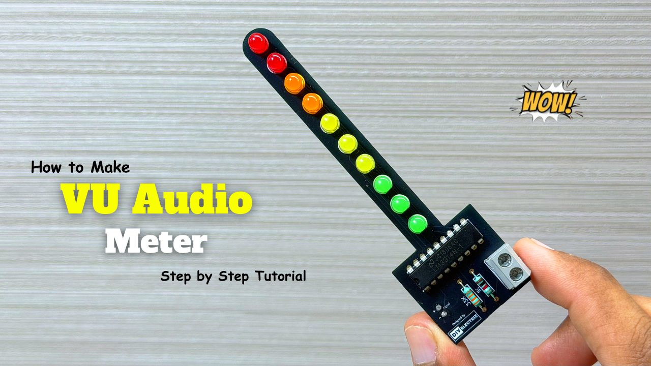
Audio Level Indicator – VU Meter
The VU meter—short for “volume unit meter”—is a device used to measure the average level of audio signals in terms of their loudness. It visually indicates the intensity of sound …
-
Powerful Audio Amplifier Using cd4440
Welcome to our latest video where we delve into the fascinating world of audio amplification using the CD4440 IC! In this comprehensive guide, we’ll walk you through the step-by-step process …
-
Building an Automatic Dark Sensor with BD139 Transistor
Light and darkness are two sides of the same coin, influencing our daily lives in ways we often overlook. Imagine a world where lights adjust themselves according to the ambient …