
Ultrasonic sensors are widely used in robotics and automation for distance measurement. By integrating a servo motor and an ultrasonic sensor, we can build a basic radar system. In this project, we will use an Arduino Uno, a HC-SR04 ultrasonic sensor, and a servo motor to create a simple radar system that sweeps across a given area and measures distances at various points.
The idea is to rotate the servo motor in increments, with the ultrasonic sensor attached, and measure the distance at each angle. The Arduino will then report the distance for each servo position, which can be displayed on a serial monitor or used for further processing.
Components Required:
- Arduino Uno: The microcontroller that will control the system.
- HC-SR04 Ultrasonic Sensor: Measures distance by emitting ultrasonic waves and calculating the time it takes for the waves to return after hitting an object.
- Servo Motor: Rotates the ultrasonic sensor to scan different angles.
- Jumper Wires: For connections.
- Breadboard: Optional, for organizing the components.
Connecting the Ultrasonic Sensor and Servo Motor to Arduino Uno
In this project, we are using an HC-SR04 ultrasonic sensor for distance measurement and a servo motor to rotate the sensor for scanning different angles. Let’s break down how to connect these components to the Arduino Uno.
Components:
- HC-SR04 Ultrasonic Sensor (for measuring distance)
- Servo Motor (for rotating the ultrasonic sensor)
- Arduino Uno (microcontroller to control the components)
1. HC-SR04 Ultrasonic Sensor Connection:
The HC-SR04 ultrasonic sensor has four pins: VCC, GND, Trig, and Echo.
- VCC (Power): Connects to the 5V pin on the Arduino (this provides the power to the ultrasonic sensor).
- GND (Ground): Connects to the GND pin on the Arduino.
- Trig (Trigger): This pin is used to send the pulse to initiate the ultrasonic measurement. Connect the Trig pin to Pin 10 on the Arduino (as defined in the code).
- Echo (Echo): This pin listens for the echo pulse and is connected to the Pin 11 on the Arduino.
2. Servo Motor Connection:
A servo motor has three pins: VCC (Power), GND (Ground), and Signal (for controlling the motor’s movement).
- VCC (Power): Connects to the 5V pin on the Arduino.
- GND (Ground): Connects to the GND pin on the Arduino.
- Signal (Control): Connects to Pin 12 on the Arduino (this is where the PWM signal is sent to control the servo motor).
Pin Configuration Summary:
| Component | Pin on Arduino Uno | Pin on the Component | Purpose |
|---|---|---|---|
| HC-SR04 Ultrasonic Sensor | Trig Pin (Pin 10) | Trig | Send Trigger Pulse |
| Echo Pin (Pin 11) | Echo | Receive Echo Pulse | |
| 5V Pin | VCC | Power to Ultrasonic Sensor | |
| GND Pin | GND | Ground for Ultrasonic Sensor | |
| Servo Motor | Pin 12 | Signal Pin | Control Servo Position |
| 5V Pin | VCC | Power to Servo Motor | |
| GND Pin | GND | Ground for Servo Motor |
Step-by-Step Connection:
1. Connect the HC-SR04 Ultrasonic Sensor:
- VCC (HC-SR04) → 5V (Arduino)
- GND (HC-SR04) → GND (Arduino)
- Trig (HC-SR04) → Pin 10 (Arduino) (This is used to send the trigger signal to start the ultrasonic pulse)
- Echo (HC-SR04) → Pin 11 (Arduino) (This is used to receive the pulse and measure the time it takes to return)
2. Connect the Servo Motor:
- VCC (Servo) → 5V (Arduino) (This powers the servo motor)
- GND (Servo) → GND (Arduino) (Ground connection)
- Signal (Servo) → Pin 12 (Arduino) (This pin controls the servo’s position)
3. Power the Arduino Uno:
- 5V Pin → Power the sensor and servo motor
- GND Pin → Ground for all components
Arduino Code:
// Includes the Servo library
#include <Servo.h>.
// Defines Tirg and Echo pins of the Ultrasonic Sensor
const int trigPin = 10;
const int echoPin = 11;
// Variables for the duration and the distance
long duration;
int distance;
Servo myServo; // Creates a servo object for controlling the servo motor
void setup() {
  pinMode(trigPin, OUTPUT); // Sets the trigPin as an Output
  pinMode(echoPin, INPUT); // Sets the echoPin as an Input
  Serial.begin(9600);
  myServo.attach(12); // Defines on which pin is the servo motor attached
}
void loop() {
  // rotates the servo motor from 15 to 165 degrees
  for(int i=15;i<=165;i++){
  myServo.write(i);
  delay(5);
  distance = calculateDistance();// Calls a function for calculating the distance measured by the Ultrasonic sensor for each degree

  Serial.print(i); // Sends the current degree into the Serial Port
  Serial.print(","); // Sends addition character right next to the previous value needed later in the Processing IDE for indexing
  Serial.print(distance); // Sends the distance value into the Serial Port
  Serial.print("."); // Sends addition character right next to the previous value needed later in the Processing IDE for indexing
  }
  // Repeats the previous lines from 165 to 15 degrees
  for(int i=165;i>15;i--){
  myServo.write(i);
  delay(5);
  distance = calculateDistance();
  Serial.print(i);
  Serial.print(",");
  Serial.print(distance);
  Serial.print(".");
  }
}
// Function for calculating the distance measured by the Ultrasonic sensor
int calculateDistance(){

  digitalWrite(trigPin, LOW);
  delayMicroseconds(2);
  // Sets the trigPin on HIGH state for 10 micro seconds
  digitalWrite(trigPin, HIGH);
  delayMicroseconds(10);
  digitalWrite(trigPin, LOW);
  duration = pulseIn(echoPin, HIGH); // Reads the echoPin, returns the sound wave travel time in microseconds
  distance= duration*0.034/2;
  return distance;
}
Processing IDE Code:
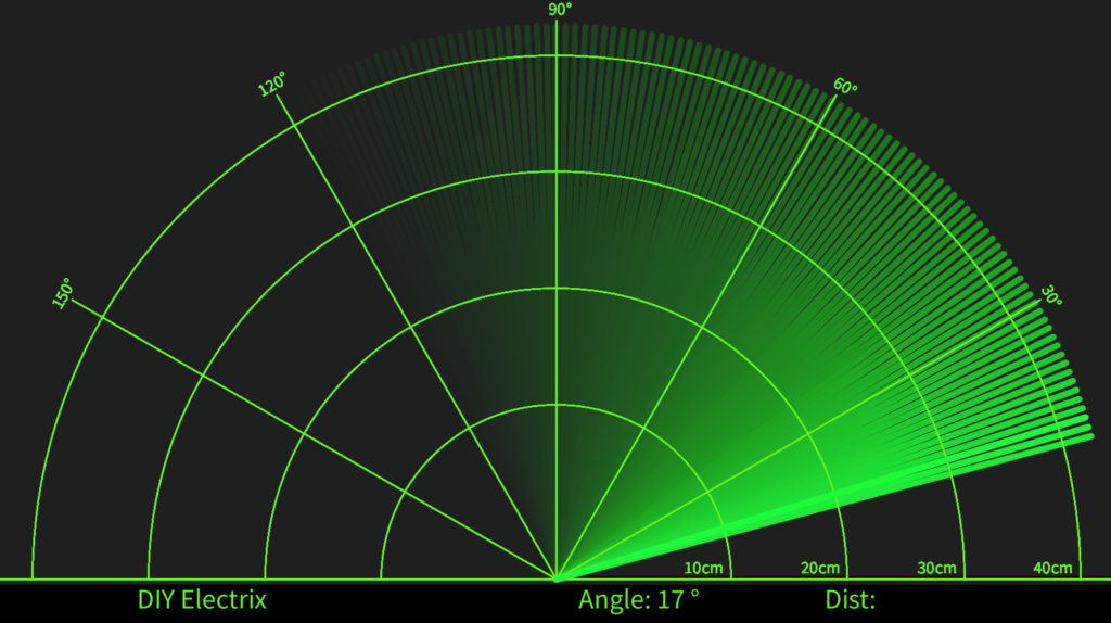
Connecting Processing with Arduino
Once you’ve connected the Arduino with the ultrasonic sensor and servo motor as previously explained, you can begin visualizing the data in Processing. The Arduino will send data (angle and distance) via the Serial port to Processing, which will use that data to draw the radar.
Steps:
- Open the Processing IDE: After installation, launch the Processing IDE.
- Write/Upload Arduino Code: First, make sure your Arduino is running the appropriate code that sends data (angle and distance) over the serial port to the computer.
- Connect the Arduino to Processing: In Processing, you’ll use the Serial library to read the data sent from the Arduino over the serial connection.
import processing.serial.*; // imports library for serial communication
import java.awt.event.KeyEvent; // imports library for reading the data from the serial port
import java.io.IOException;
Serial myPort; // defines Object Serial
// defubes variables
String angle="";
String distance="";
String data="";
String noObject;
float pixsDistance;
int iAngle, iDistance;
int index1=0;
int index2=0;
PFont orcFont;
void setup() {

 size (1600, 900); // ***CHANGE THIS TO YOUR SCREEN RESOLUTION***
 smooth();
 myPort = new Serial(this,"COM11", 9600); // starts the serial communication
 myPort.bufferUntil('.'); // reads the data from the serial port up to the character '.'. So actually it reads this: angle,distance.
}
void draw() {

  fill(98,245,31);
  // simulating motion blur and slow fade of the moving line
  noStroke();
  fill(0,4);
  rect(0, 0, width, height-height*0.065);

  fill(98,245,31); // green color
  // calls the functions for drawing the radar
  drawRadar();
  drawLine();
  drawObject();
  drawText();
}
void serialEvent (Serial myPort) { // starts reading data from the Serial Port
  // reads the data from the Serial Port up to the character '.' and puts it into the String variable "data".
  data = myPort.readStringUntil('.');
  data = data.substring(0,data.length()-1);

  index1 = data.indexOf(","); // find the character ',' and puts it into the variable "index1"
  angle= data.substring(0, index1); // read the data from position "0" to position of the variable index1 or thats the value of the angle the Arduino Board sent into the Serial Port
  distance= data.substring(index1+1, data.length()); // read the data from position "index1" to the end of the data pr thats the value of the distance

  // converts the String variables into Integer
  iAngle = int(angle);
  iDistance = int(distance);
}
void drawRadar() {
  pushMatrix();
  translate(width/2,height-height*0.074); // moves the starting coordinats to new location
  noFill();
  strokeWeight(2);
  stroke(98,245,31);
  // draws the arc lines
  arc(0,0,(width-width*0.0625),(width-width*0.0625),PI,TWO_PI);
  arc(0,0,(width-width*0.27),(width-width*0.27),PI,TWO_PI);
  arc(0,0,(width-width*0.479),(width-width*0.479),PI,TWO_PI);
  arc(0,0,(width-width*0.687),(width-width*0.687),PI,TWO_PI);
  // draws the angle lines
  line(-width/2,0,width/2,0);
  line(0,0,(-width/2)*cos(radians(30)),(-width/2)*sin(radians(30)));
  line(0,0,(-width/2)*cos(radians(60)),(-width/2)*sin(radians(60)));
  line(0,0,(-width/2)*cos(radians(90)),(-width/2)*sin(radians(90)));
  line(0,0,(-width/2)*cos(radians(120)),(-width/2)*sin(radians(120)));
  line(0,0,(-width/2)*cos(radians(150)),(-width/2)*sin(radians(150)));
  line((-width/2)*cos(radians(30)),0,width/2,0);
  popMatrix();
}
void drawObject() {
  pushMatrix();
  translate(width/2,height-height*0.074); // moves the starting coordinats to new location
  strokeWeight(9);
  stroke(255,10,10); // red color
  pixsDistance = iDistance*((height-height*0.1666)*0.025); // covers the distance from the sensor from cm to pixels
  // limiting the range to 40 cms
  if(iDistance<40){
    // draws the object according to the angle and the distance
  line(pixsDistance*cos(radians(iAngle)),-pixsDistance*sin(radians(iAngle)),(width-width*0.505)*cos(radians(iAngle)),-(width-width*0.505)*sin(radians(iAngle)));
  }
  popMatrix();
}
void drawLine() {
  pushMatrix();
  strokeWeight(9);
  stroke(30,250,60);
  translate(width/2,height-height*0.074); // moves the starting coordinats to new location
  line(0,0,(height-height*0.12)*cos(radians(iAngle)),-(height-height*0.12)*sin(radians(iAngle))); // draws the line according to the angle
  popMatrix();
}
void drawText() { // draws the texts on the screen

  pushMatrix();
  if(iDistance>40) {
  noObject = "Out of Range";
  }
  else {
  noObject = "In Range";
  }
  fill(0,0,0);
  noStroke();
  rect(0, height-height*0.0648, width, height);
  fill(98,245,31);
  textSize(25);

  text("10cm",width-width*0.3854,height-height*0.0833);
  text("20cm",width-width*0.281,height-height*0.0833);
  text("30cm",width-width*0.177,height-height*0.0833);
  text("40cm",width-width*0.0729,height-height*0.0833);
  textSize(40);
  text("DIY Electrix", width-width*0.875, height-height*0.0277);
  text("Angle: " + iAngle +" °", width-width*0.48, height-height*0.0277);
  text("Dist: ", width-width*0.26, height-height*0.0277);
  if(iDistance<40) {
  text("        " + iDistance +" cm", width-width*0.225, height-height*0.0277);
  }
  textSize(25);
  fill(98,245,60);
  translate((width-width*0.4994)+width/2*cos(radians(30)),(height-height*0.0907)-width/2*sin(radians(30)));
  rotate(-radians(-60));
  text("30°",0,0);
  resetMatrix();
  translate((width-width*0.503)+width/2*cos(radians(60)),(height-height*0.0888)-width/2*sin(radians(60)));
  rotate(-radians(-30));
  text("60°",0,0);
  resetMatrix();
  translate((width-width*0.507)+width/2*cos(radians(90)),(height-height*0.0833)-width/2*sin(radians(90)));
  rotate(radians(0));
  text("90°",0,0);
  resetMatrix();
  translate(width-width*0.513+width/2*cos(radians(120)),(height-height*0.07129)-width/2*sin(radians(120)));
  rotate(radians(-30));
  text("120°",0,0);
  resetMatrix();
  translate((width-width*0.5104)+width/2*cos(radians(150)),(height-height*0.0574)-width/2*sin(radians(150)));
  rotate(radians(-60));
  text("150°",0,0);
  popMatrix();
}
More Projects
-
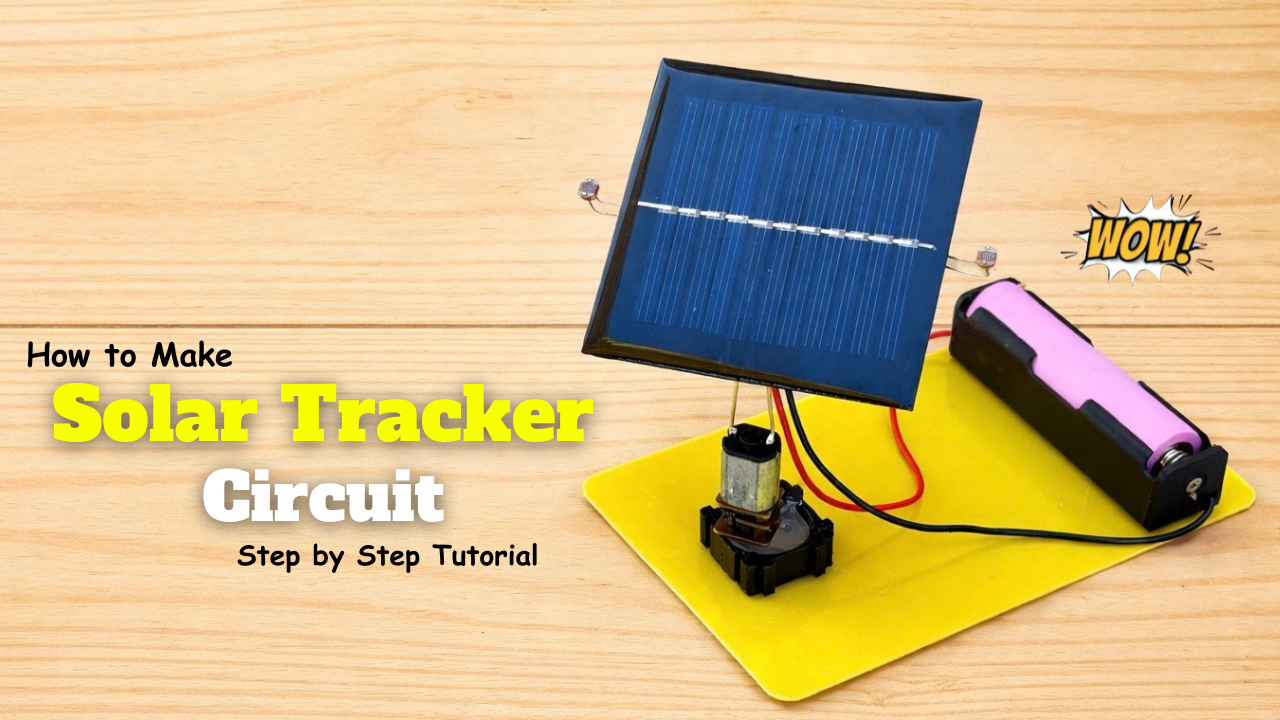
How to Make a Automatic Solar Tracker – Step by Step!
A sun tracker is a system designed to orient a solar panel or a solar collector to maximize its exposure to sunlight throughout the day. It typically involves sensors to …
-
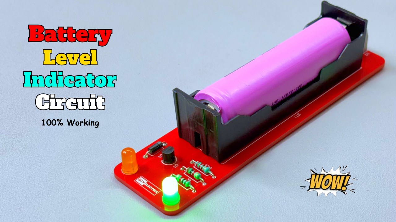
Build a 3.7V 18650 Battery Level Indicator using BC547 Transistors
Lithium-ion 18650 batteries are widely used in DIY projects, power banks, and portable electronics. But to ensure safety and efficiency, it’s important to monitor their voltage levels. In this blog, …
-
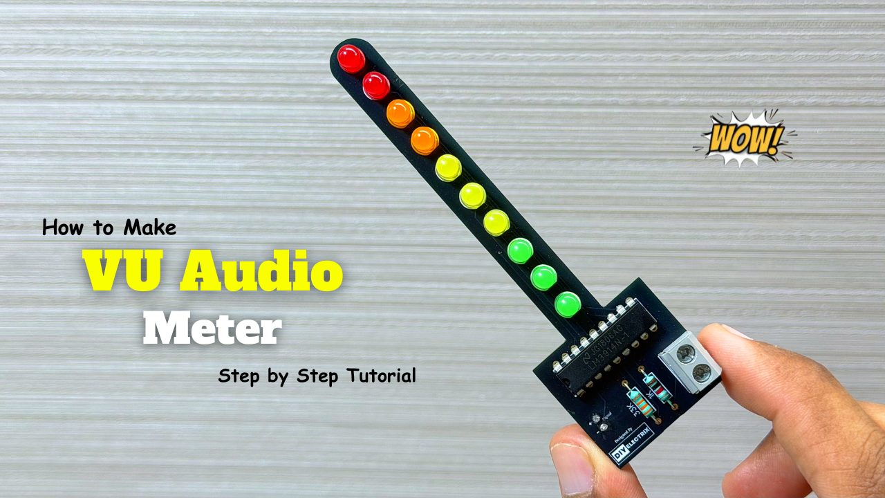
Audio Level Indicator – VU Meter
The VU meter—short for “volume unit meter”—is a device used to measure the average level of audio signals in terms of their loudness. It visually indicates the intensity of sound …