
Building an 8S (8 series) LiFePO4 battery pack using LiFePO4 cells and a Daly Battery Management System (BMS). If you’re planning your own DIY power storage project, this guide might help you get started!
Why LiFePO4?
Lithium Iron Phosphate (LiFePO4) batteries have gained popularity for their safety, long lifespan, and thermal stability. Compared to standard lithium-ion batteries, LiFePO4 cells can handle more charge cycles (2000-5000), making them perfect for applications like solar storage, electric vehicles, and DIY backup systems.
Components I Used:
- 8 x LiFePO4 Cells (3.2V nominal, 24 – 37Ah each)
- Daly 8S BMS (24V rated, with balancing and protection features)
- Nickel strips for cell interconnection
- Spot welder
- XT60 connectors
- Heat shrink tubing
- Multimeter and basic tools
What Is BMS?
A BMS stands for Battery Management System. It’s an electronic system that manages and protects rechargeable batteries — especially in packs like your LiFePO4 8S setup.
Key functions of a BMS:
- ✅ Overcharge protection (prevents damage from too high voltage)
- ✅ Over-discharge protection (prevents deep discharge that can ruin cells)
- ✅ Short-circuit protection (cuts off power in case of a fault)
- ✅ Cell balancing (keeps all cells at the same voltage to extend lifespan)
- ✅ Temperature monitoring (some advanced BMSs monitor heat to avoid thermal issues)
Configuration: 8S
- 8S means 8 cells connected in series.
- Each LiFePO4 cell = 3.2V nominal.
- So, 8 x 3.2V = 25.6V nominal (and about 29.2V when fully charged).
This makes it suitable for 24V systems like solar inverters, e-bikes, and portable power stations.
Circuit Diagram:

Assembly Steps:
- Planning the Layout
- I arranged the 8 cells in a straight line to keep the design compact.
- Spot Welding the Cells
- Used nickel strips and a spot welder to connect the cells in series.
- Double-checked the polarity and voltages after each connection.
- Connecting the Daly 8S BMS
- The Daly BMS is the brain of the battery, providing overcharge, over-discharge, and short-circuit protection.
- Connected the balance leads to each cell, following the 8S wiring diagram provided by Daly.
- Final Checks
- Measured total pack voltage (should be around 25.6V).
- Checked individual cell voltages for balance.
- Wrapping and Finishing
- Wrapped the pack with heat shrink for insulation and added XT60 connectors for easy connection.
Testing the Pack:
Once assembled, I tested the pack with a 24V inverter and a small load. The Daly BMS handled the balancing and protection well, and the pack performed smoothly. I monitored the temperatures and voltage during the first few charge/discharge cycles.
Applications:
- Solar energy storage
- DIY powerwall projects
- Portable battery backup
- E-bikes and scooters
Tips for Builders:
- Always double-check BMS wiring—it’s the most critical part!
- Use proper insulation to avoid shorts.
- Don’t skip balance charging during the initial setup.
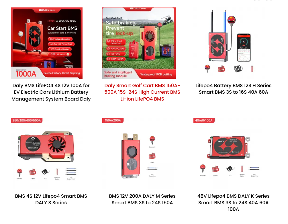
DALY BMS:

The Daly K-Series Smart BMS is a powerful and intelligent Battery Management System designed for lithium iron phosphate (LiFePO₄) and lithium-ion batteries. It supports 3S to 24S configurations and is available in 40A, 60A, and 100A versions, making it ideal for a wide range of applications including electric vehicles, solar energy storage, and backup power systems.
With built-in communication options like CAN, RS485, and UART, users can monitor and adjust settings in real time via a mobile app or PC software.
What is an LFP Cell?
LFP stands for Lithium Iron Phosphate (LiFePO₄).
It is a type of lithium-ion battery chemistry popularly used in electric vehicles, solar systems, power banks, and energy storage devices.
Key Features of LFP Cells
1. Very Safe (High Thermal Stability)
- LFP batteries do not overheat easily.
- Much lower risk of fire or explosion compared to other lithium batteries like NMC or NCA.
2. Long Cycle Life
- Typically 2,000 to 4,000 charge cycles.
- Can last 8–12 years easily.
3. Excellent Temperature Performance
- Works well in hot environments.
- Slightly weaker performance in cold temperatures.
4. Environment-Friendly Chemistry
- Contains no cobalt or nickel.
- Non-toxic and more recyclable.
5. Stable Voltage Output
- Nominal voltage: 3.2V
- Full charge: 3.65V
- Safe discharge limit: 2.5V (min)
Technical Specifications (Typical LFP Cell)
| Parameter | Value |
|---|---|
| Chemistry | LiFePO₄ |
| Nominal Voltage | 3.2 V |
| Fully Charged Voltage | 3.65 V |
| Capacity | 10Ah – 300Ah (varies) |
| Cycle Life | 2000–4000+ cycles |
| Operating Temp | −20°C to 60°C |
| Energy Density | Lower than NMC (but safer) |
Where LFP Cells Are Commonly Used
- Electric vehicles (EVs)
- Solar home systems & inverters
- Portable power stations
- E-rickshaws, e-scooters
- UPS & backup systems
Advantages vs Disadvantages
Advantages
- Very safe
- Long life
- Affordable
- Good thermal stability
- No toxic metals
Disadvantages
- Lower energy density
- Slightly heavier
- Performance drops in freezing temperatures
More Projects
-
Audio Level Indicator – VU Meter
The VU meter—short for “volume unit meter”—is a device used to measure the average level of audio signals in terms of their loudness. It visually indicates the intensity of sound …
-
Powerful Audio Amplifier Using cd4440
Welcome to our latest video where we delve into the fascinating world of audio amplification using the CD4440 IC! In this comprehensive guide, we’ll walk you through the step-by-step process …
-
Building an Automatic Dark Sensor with BD139 Transistor
Light and darkness are two sides of the same coin, influencing our daily lives in ways we often overlook. Imagine a world where lights adjust themselves according to the ambient …