
Proximity Sensor :
Proximity sensors are devices that detect the presence or absence of an object within their proximity without any physical contact. They utilize various technologies to sense changes in the surrounding environment and provide valuable information for controlling and automating systems.
Components Used :
- BC547
- LED
- Buzzer
- 56k ohm Resistor
- 100 ohm Resistor
- 220Ohm Resistor
- Ir Reciever and Transmitter
- 9v Battery And Cap
Circuit Diagram :
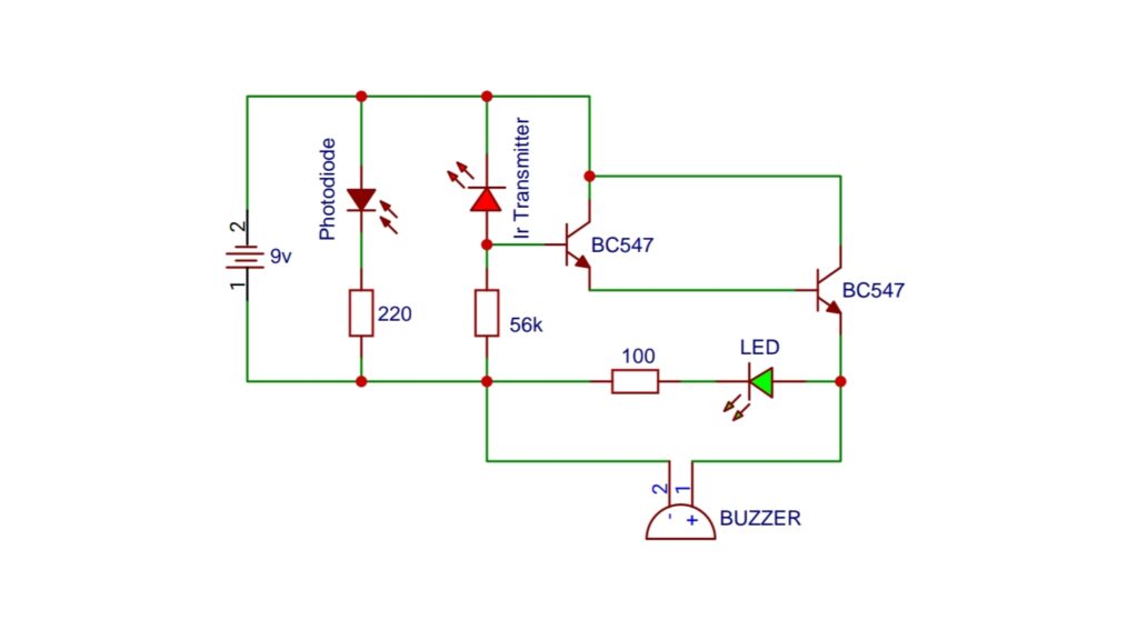
BC547 NPN Transistor :
The BC547 is a general-purpose NPN bipolar junction transistor (BJT) with three layers of semiconductor material. The layers consist of a P-type semiconductor, an N-type semiconductor, and another P-type semiconductor. The “NPN” designation indicates the arrangement of these layers. The BC547 transistor is housed in a small TO-92 package, making it easy to handle and integrate into circuits.
Pin Configuration:
Understanding the pin configuration of the BC547 transistor is crucial for proper utilization. The transistor has three pins – collector (C), base (B), and emitter (E). When looking at the flat side of the transistor with the pins facing down, the pins are arranged from left to right as follows: collector, base, and emitter.
1. Collector (C): This is the power supply pin and is connected to the positive side of the circuit.
2. Base (B): The base pin controls the flow of current between the collector and emitter. It receives a small input current that controls a much larger output current.
3. Emitter (E): The emitter pin is the output of the transistor, allowing the controlled current to flow to the ground.
Characteristics and Specifications:
The BC547 transistor has several key characteristics and specifications that make it versatile for various applications:
– Maximum Collector Current (Ic): The BC547 can handle a maximum collector current of around 100mA, making it suitable for low to moderate power applications.
– Collector-Emitter Voltage (Vce): The maximum voltage across the collector and emitter pins is typically around 45V, allowing for use in circuits with varying voltage levels.
– DC Current Gain (hfe): The DC current gain of the BC547 is in the range of 110 to 800, indicating its ability to amplify input signals.
Applications:
The BC547 NPN transistor finds application in a wide range of electronic circuits, including:
1. Amplifiers: Due to its ability to amplify small input signals, the BC547 is commonly used in audio amplifiers and signal processing circuits.
2. Switching Circuits: As an NPN transistor, the BC547 is frequently employed as a switch in digital and control circuits.
3. Oscillators: The transistor’s amplification properties make it suitable for use in oscillator circuits, generating repetitive waveforms.
4. Signal Modulation: In communication systems, the BC547 can be used to modulate signals for transmission.
Using the BC547 Transistor in a Circuit:
To use the BC547 transistor in a circuit, consider the following steps:
1. Connect the collector pin to the positive power supply.
2. Connect the emitter pin to the ground.
3. Apply the input signal to the base pin.
4. Monitor the output signal at the collector pin.
Remember to refer to the transistor’s datasheet for specific values and recommendations based on your circuit requirements.
Conclusion:
The BC547 NPN transistor is a versatile and widely used component in the world of electronics. Its applications range from amplification to switching, making it a valuable tool for hobbyists and professionals alike. Understanding its pin configuration, characteristics, and specifications is essential for effectively integrating it into electronic circuits. Experimenting with the BC547 in various circuits can lead to a deeper understanding of transistor behavior and enhance your skills in electronic design.
Piezo Buzzer :
The magic behind the piezo buzzer lies in the piezoelectric effect, a phenomenon where certain materials generate an electric charge in response to mechanical stress. In the case of piezo buzzers, a piezoelectric crystal deforms when subjected to an electric field, creating mechanical vibrations that, in turn, produce sound waves.
Anatomy of a Piezo Buzzer:
A typical piezo buzzer consists of the following components:
1. Piezoelectric Element: This is the heart of the buzzer, usually a ceramic disc or crystal that undergoes deformation when an electrical voltage is applied.
2. Diaphragm: Connected to the piezoelectric element, the diaphragm amplifies the mechanical vibrations, producing audible sound waves.
3. Casing: The outer casing protects the internal components and influences the directionality and resonance characteristics of the sound produced.
Working Principles:
When a voltage is applied to the piezoelectric element, it deforms, causing the diaphragm to vibrate. These vibrations generate sound waves, creating audible tones. The frequency and intensity of the sound depend on the applied voltage, the properties of the piezoelectric material, and the design of the buzzer.
Applications of Piezo Buzzers:
1. Alarm Systems: Piezo buzzers are commonly used in alarm systems, providing audible alerts for various situations such as security breaches or fire alarms.
2. Electronic Devices: Many electronic devices, including timers, watches, and kitchen appliances, use piezo buzzers for sound notifications.
3. DIY Projects: Hobbyists and electronics enthusiasts often incorporate piezo buzzers into their projects for creating interactive sound effects or alarms.
4. Industrial Equipment: In industrial settings, piezo buzzers are employed for signaling purposes and as warning devices.
Using Piezo Buzzers in Projects:
Incorporating a piezo buzzer into your electronic project is relatively straightforward. Here’s a simple guide:
1. Connection: Connect the positive terminal of the piezo buzzer to the positive voltage source and the negative terminal to the ground.
2. Voltage Control: Adjust the voltage supplied to control the pitch and intensity of the sound. Experiment with different voltage levels to achieve the desired effect.
3. Frequency Selection: Some piezo buzzers come with built-in oscillators, allowing you to produce different frequencies without external circuitry. Check the datasheet for details.
Conclusion:
Piezo buzzers may be small in size, but they play a big role in the world of electronics. Their simplicity, reliability, and cost-effectiveness make them indispensable for a wide range of applications. Whether you’re designing an alarm system, tinkering with DIY projects, or enhancing electronic devices, the piezo buzzer is a valuable component that brings audible life to your creations. Understanding the principles and applications of piezo buzzers opens up a world of possibilities for adding sound to your electronic endeavors.
IR Transmitter :
An IR transmitter is a device that emits infrared light, which is not visible to the human eye but is crucial for wireless communication and control applications. Typically, IR transmitters are used in conjunction with IR receivers to establish a seamless link for transmitting data, commands, or control signals.
Working Principles:
IR transmitters operate on the principle of modulating infrared light to encode information. This modulation can take various forms, such as amplitude modulation (AM) or frequency modulation (FM). The modulation process allows the transmission of data by altering the intensity or frequency of the infrared light.
Components of an IR Transmitter:
1. IR Light Source: The heart of the IR transmitter, usually an IR light-emitting diode (IR LED), emits infrared light when subjected to an electric current.
2. Modulation Circuit: This circuit controls the modulation of the IR light, encoding information onto the transmitted signal.
3. Power Supply: To energize the IR LED and the modulation circuit, a stable power supply is essential for consistent and reliable operation.
Applications of IR Transmitters:
1. Remote Controls: Perhaps the most common application of IR transmitters is in remote control systems for TVs, audio systems, air conditioners, and other electronic devices. The IR transmitter encodes commands, and the corresponding IR receiver on the device decodes and executes them.
2. Infrared Data Transmission: IR transmitters are used for short-range data transmission between devices, such as sending files between smartphones or connecting peripherals like keyboards and mice to computers.
3. Automatic Door Openers: Infrared sensors equipped with transmitters are often used in automatic door opening systems, detecting the presence of a person and triggering the door to open.
4. Proximity Sensors: IR transmitters, when paired with IR receivers, are employed in proximity sensors for detecting objects in various applications, including robotics and automation.
Building an IR Transmitter Circuit:
Creating a simple IR transmitter circuit involves connecting an IR LED to a power source and adding a modulation circuit to encode data. A resistor is often used to limit the current flowing through the IR LED.
Conclusion:
IR transmitters, though inconspicuous, play a pivotal role in our daily lives, enabling seamless communication and control in numerous electronic devices. From the humble TV remote to advanced data transmission systems, IR transmitters contribute to the efficiency, convenience, and functionality of modern electronics. As technology continues to evolve, so does the role of IR transmitters, ensuring that the invisible signals they emit continue to shape the interconnected world we live in. Understanding the principles and applications of IR transmitters opens up possibilities for innovation and creativity in the realm of electronics.
IR Receiver
An IR receiver is a device that detects and decodes infrared signals sent by IR transmitters. It converts modulated infrared light into electrical signals that can be interpreted and acted upon by electronic systems. Commonly found in remote control systems and various electronic devices, IR receivers are integral to the user-friendly and efficient operation of numerous applications.
How IR Receivers Work:
1. IR Sensor: The core of an IR receiver is an IR sensor, typically a photodiode or phototransistor. These sensors are sensitive to infrared light and can detect the modulated signals sent by IR transmitters.
2. Demodulation Circuit: The detected signals are then passed through a demodulation circuit, which extracts the encoded information from the modulated signal. This process allows the receiver to discern specific commands or data.
3. Decoding Logic: The decoded information is further processed by decoding logic, which interprets the received signals and translates them into actionable commands for the connected electronic device.
Components of an IR Receiver:
1. IR Sensor: As mentioned, the IR sensor is a critical component that senses infrared light and generates electrical signals in response to modulated IR signals.
2. Demodulation Circuit: This circuit separates the modulated signals from the carrier frequency, revealing the original information encoded by the IR transmitter.
3. Decoding Logic: The decoding logic is responsible for interpreting the received signals and translating them into meaningful commands or data.
Applications of IR Receivers:
1. Remote Control Systems: The most common application of IR receivers is in remote control systems for TVs, audio systems, and other electronic devices. IR receivers decode signals from the remote control, allowing users to command and control their devices effortlessly.
2. Home Automation: IR receivers are used in smart home systems to interpret signals from remote controls or mobile apps, enabling users to control lighting, air conditioning, and other smart devices.
3. Infrared Data Transmission: IR receivers facilitate short-range data transmission between devices, such as wirelessly transferring files between smartphones or connecting peripherals like keyboards and mice to computers.
4. Security Systems: Infrared sensors equipped with IR receivers play a crucial role in security systems, detecting signals from motion detectors or door/window sensors to trigger alarms.
Incorporating IR Receivers into Projects:
Integrating an IR receiver into a project involves connecting it to a microcontroller or other processing unit capable of interpreting the decoded signals. This allows for the implementation of specific actions or responses based on the received IR commands.
Conclusion:
IR receivers may work behind the scenes, but their impact on the functionality and convenience of modern electronics is undeniable. From the familiar TV remote to advanced smart home systems, these devices play a key role in bridging the gap between user commands and electronic responses. Understanding the inner workings of IR receivers opens up avenues for innovation, empowering engineers, hobbyists, and enthusiasts to create intuitive and responsive electronic systems in various applications.
-
Audio Level Indicator – VU Meter
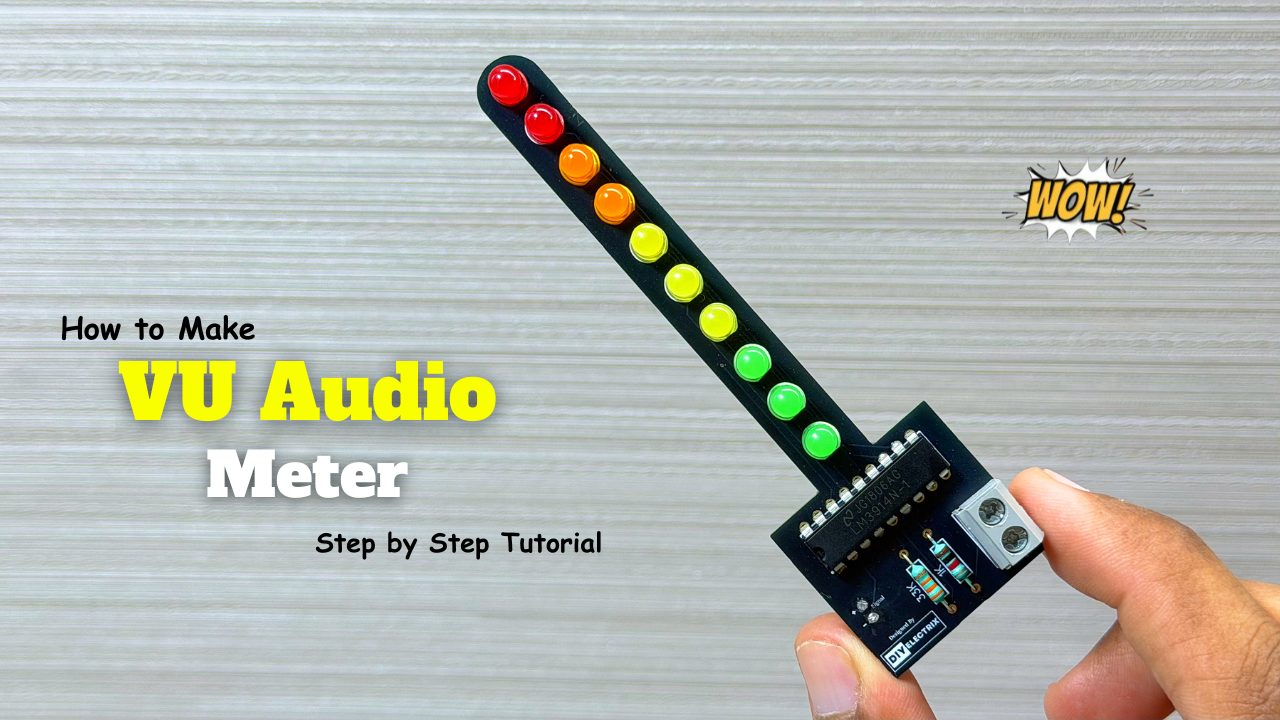
The VU meter—short for “volume unit meter”—is a device used to measure the average level of audio signals in terms of their loudness. It visually indicates the intensity of sound …
-
Powerful Audio Amplifier Using cd4440
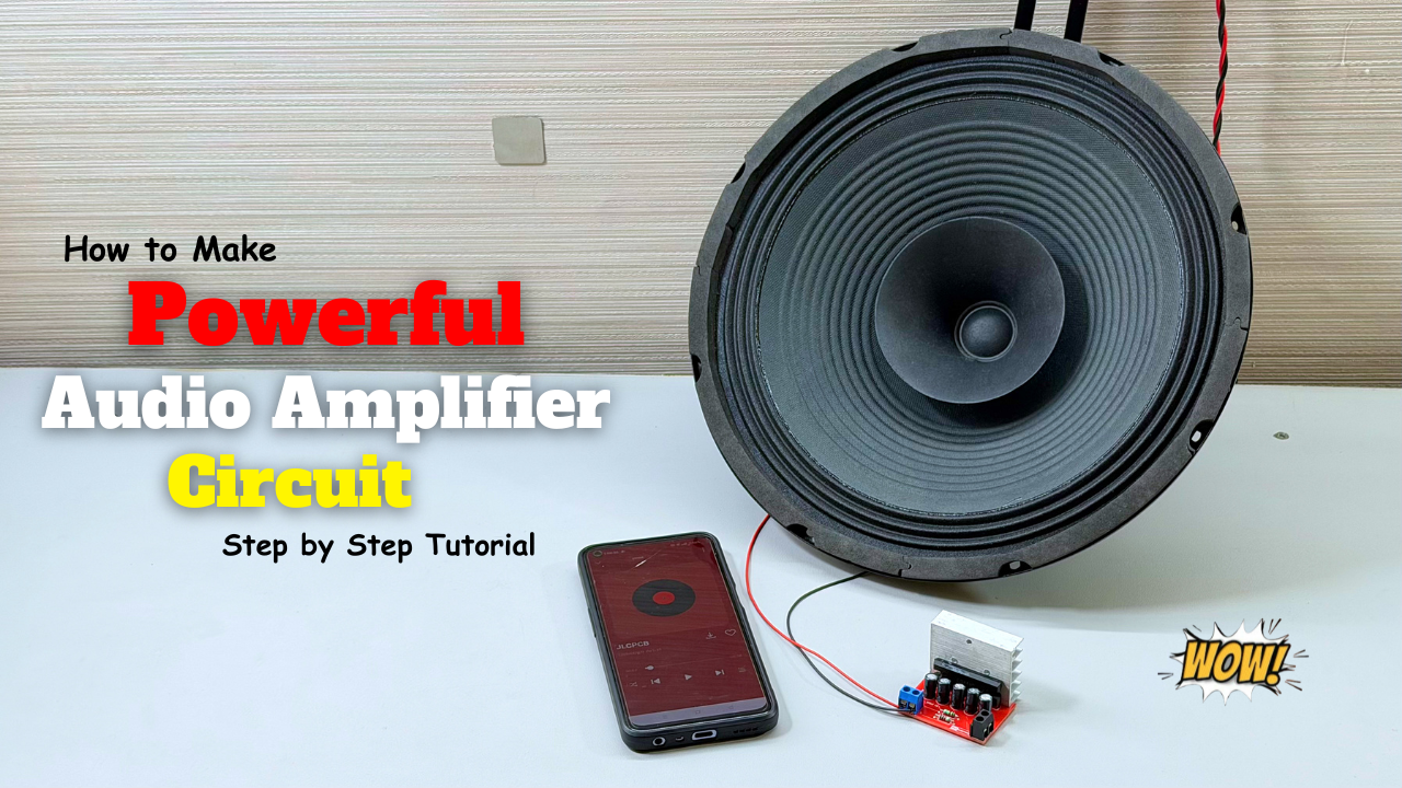
Welcome to our latest video where we delve into the fascinating world of audio amplification using the CD4440 IC! In this comprehensive guide, we’ll walk you through the step-by-step process …
-
Building an Automatic Dark Sensor with BD139 Transistor
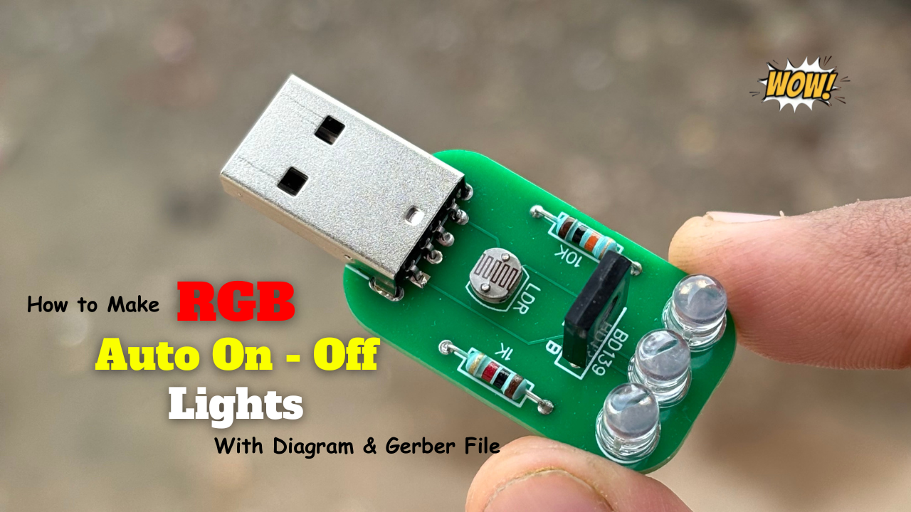
Light and darkness are two sides of the same coin, influencing our daily lives in ways we often overlook. Imagine a world where lights adjust themselves according to the ambient …