
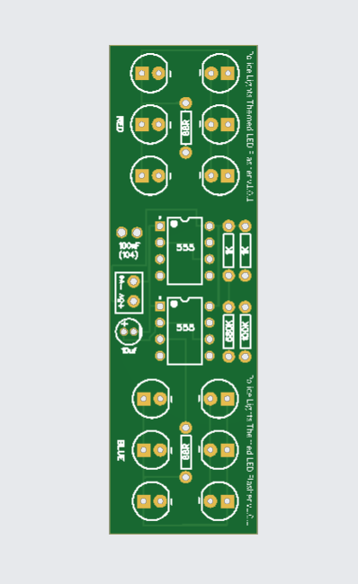
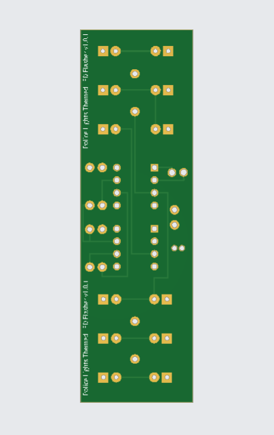
A Police Strobe Light Chaser Circuit is an electronic circuit designed to mimic the flashing red and blue lights used on police vehicles. It alternately flashes groups of LEDs (commonly red and blue) in a strobe or chasing pattern, creating a visually dynamic effect similar to real police beacons.
Components Used:
- 555 Timer IC
- Red LED
- Blue LED
- 10uf Capacitor
- 104 Capacitor
- 680k Resistor
- 100k Resistor
- 1k Resistor
- 68R Resistor
Special Thanks to Our Sponser – JLCPCB:
No project is complete without the right tool and materials. That’s why our sponser JLCPCB stepped into provide essential material for the project. JLCPCB is a leading provider of high quality printed circuit board and PCB assembling services.
Simply head over to JLCPCB, Upload your gerber file, select specification and just place your order.
48-Hour Turnaround for 6 Layer PCBs!

$0 for 2u” ENIG. Free Via-in-Pad. High Precision. Sign Up to Get $80 New User Coupons.
How To Order PCB
Gerber File:
Basic Definition
The 555 Timer IC is a small electronic chip that can produce accurate time delays or square wave signals.
It can operate in three main modes:
- Monostable mode – produces a single pulse when triggered.
- Astable mode – generates a continuous stream of pulses (like a clock).
- Bistable mode – works like a flip-flop, having two stable states (ON and OFF).
Pin Configuration (8 Pins)
| Pin No. | Name | Function |
|---|---|---|
| 1 | GND | Connected to ground (0V). |
| 2 | Trigger | Starts the timing interval when voltage drops below 1/3 of supply. |
| 3 | Output | Provides the output signal (HIGH or LOW). |
| 4 | Reset | Resets the timer when pulled LOW. |
| 5 | Control Voltage | Used to adjust threshold voltage (usually connected to ground via a capacitor). |
| 6 | Threshold | Ends the timing when voltage reaches 2/3 of supply. |
| 7 | Discharge | Discharges the timing capacitor to restart the cycle. |
| 8 | VCC | Power supply (+4.5V to +15V). |
Internal Structure
Inside the 555 timer are:
- Two comparators (compare voltages),
- One flip-flop (stores ON/OFF state),
- One discharge transistor, and
- Voltage divider made of 3 resistors (each 5kΩ — that’s where “555” comes from).
Operating Modes
1. Astable Mode
- No stable state (it continuously switches between HIGH and LOW).
- Used for generating clock pulses, LED blinkers, or tone generation.
2. Monostable Mode
- Has one stable state (LOW).
- Produces a single output pulse when triggered.
- Used in timers, pulse width control, and delay circuits.
3. Bistable Mode
- Two stable states — can be set or reset manually.
- Used in flip-flop, switch debouncing, or memory applications.
Applications
- LED Flasher / Blinker
- Police light chaser
- Pulse generator
- Delay timer
- PWM (Pulse Width Modulation) controller
- Tone generator (for sound circuits)
More Projects
-
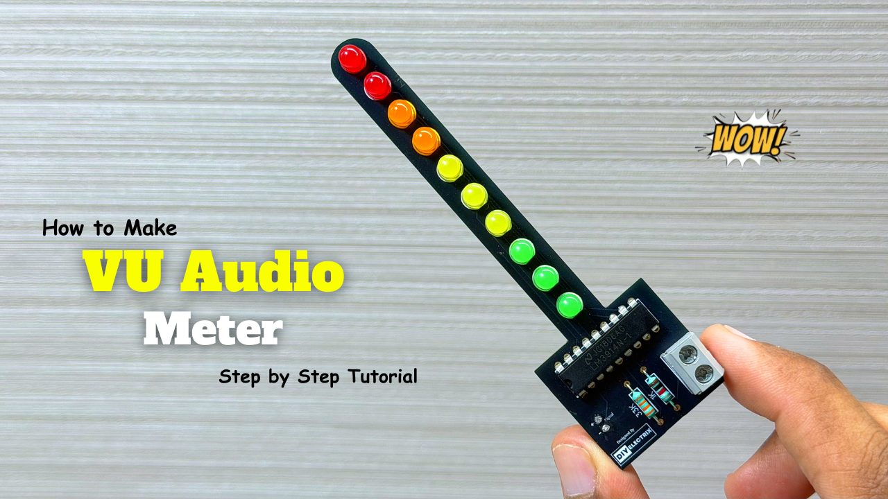
Audio Level Indicator – VU Meter
The VU meter—short for “volume unit meter”—is a device used to measure the average level of audio signals in terms of their loudness. It visually indicates the intensity of sound …
-
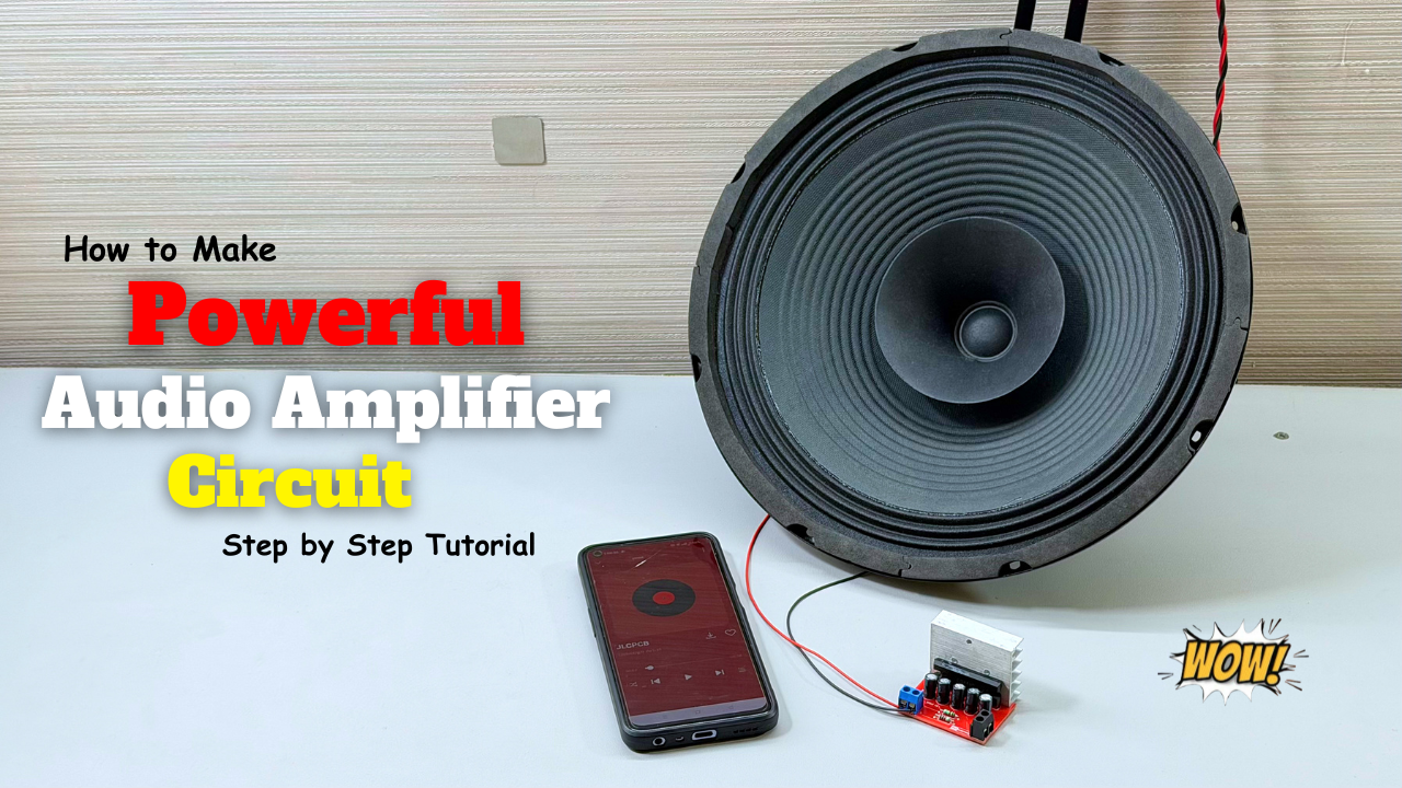
Powerful Audio Amplifier Using cd4440
Welcome to our latest video where we delve into the fascinating world of audio amplification using the CD4440 IC! In this comprehensive guide, we’ll walk you through the step-by-step process …
-
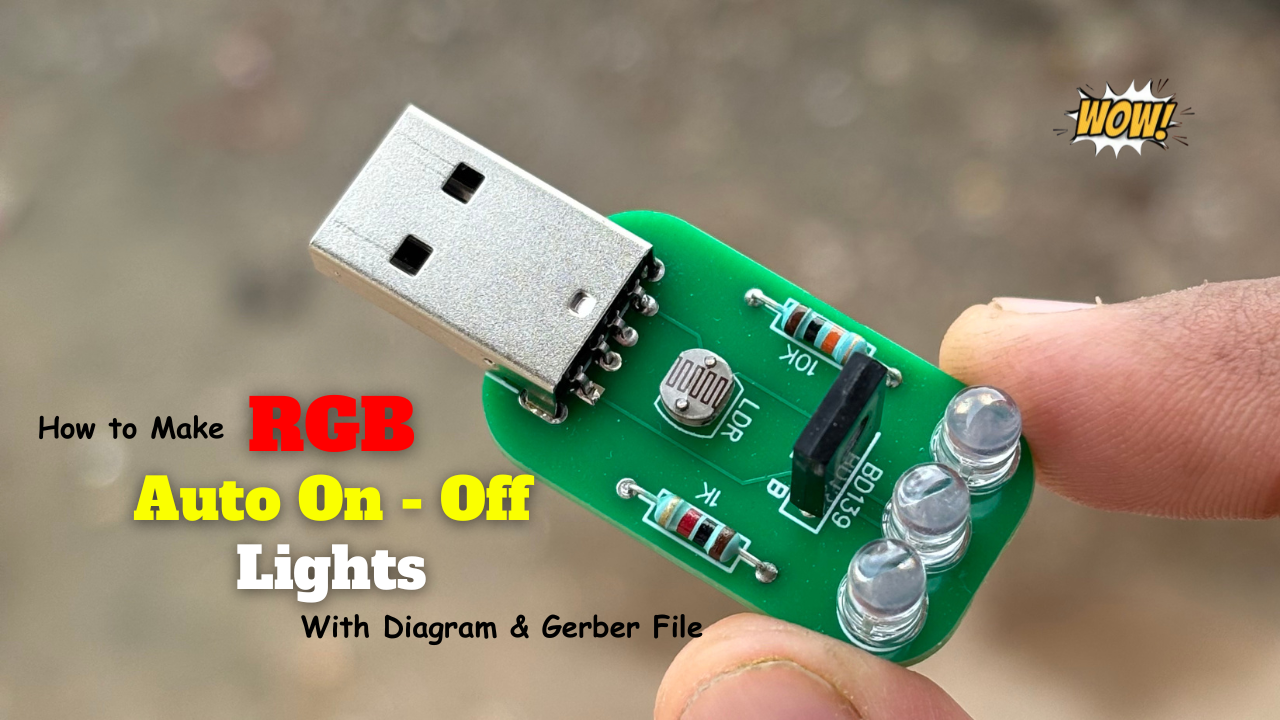
Building an Automatic Dark Sensor with BD139 Transistor
Light and darkness are two sides of the same coin, influencing our daily lives in ways we often overlook. Imagine a world where lights adjust themselves according to the ambient …