
In a world where security is becoming more important every day, building your own electronic password-based lock is not just a rewarding project — it’s also a practical one. In this post, I’ll walk you through how I built a simple but effective electronic lock system using the classic CD4013 (D Flip-Flop) and CD4011 (Nand Logic) ICs — all without a microcontroller
How It Works:
This lock operates on a fixed-sequence password using pure logic gates and flip-flops:
After the final correct key is pressed, the last flip-flop outputs a HIGH signal to unlock the system (e.g., light up an LED or activate a relay)
Each button is tied to a logic combination.
When the correct buttons are pressed in the right order, the logic gates (CD4011) enable a chain of CD4013 flip-flops to advance.
Pressing the wrong button at any stage triggers the reset line, which clears the flip-flops and starts over.
Components Required:
- CD1013 IC
- CD4017 IC
- Push Button
- Power Supply 3.7v-5v
- Resistor 1k Ohm
- Capacitor 10uf
- Solenoid Door Lock
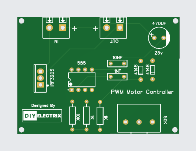
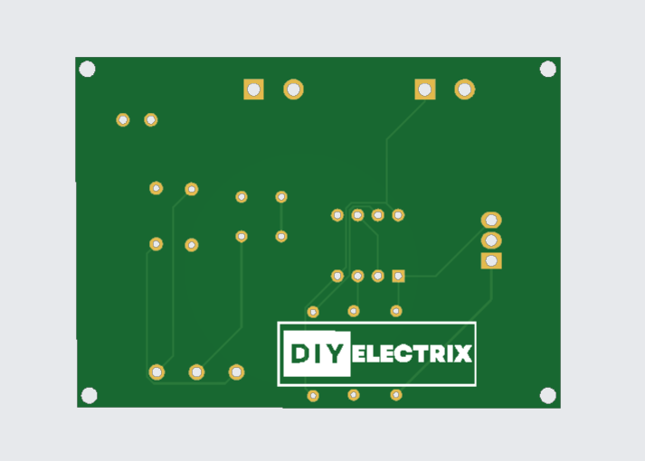
Gerber File:
Special Thanks to Our Sponser – JLCPCB:
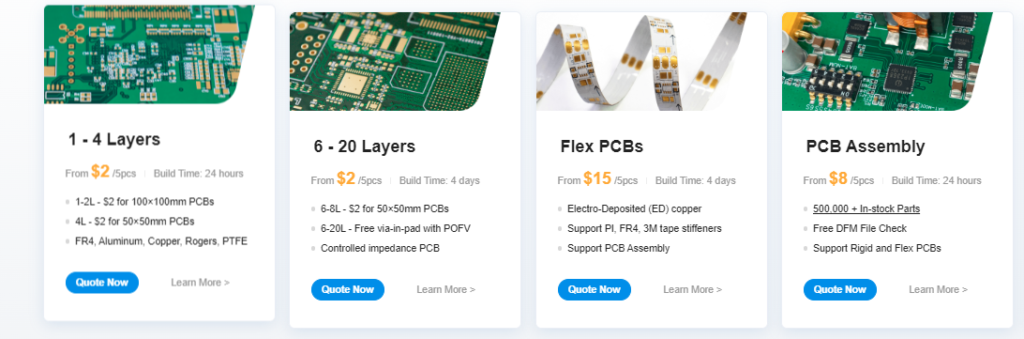
No project is complete without the right tool and materials. That’s why our sponser JLCPCB stepped into provide essential material for the project. JLCPCB is a leading provider of high quality printed circuit board and PCB assembling services.
Simply head over to JLCPCB, Upload your gerber file, select specification and just place your order.
48-Hour Turnaround for 6 Layer PCBs!
Discover Easy, Affordable, and Reliable PCB manufacturing with JLCPCB! Register to get $60 New customer coupons.
How To Order PCB
CD1013 IC:
The CD1013 is a dual general-purpose operational amplifier (op-amp) IC. It is commonly used in analog signal processing tasks like amplification, filtering, and mathematical operations such as addition, subtraction, integration, and differentiation. It is similar in function to the popular LM358 op-amp.
Key Features:
- Dual op-amp: Contains two independent op-amps in a single package.
- Wide voltage range: Operates typically from a single supply (e.g., +3V to +32V) or dual supply (e.g., ±1.5V to ±16V).
- Low power consumption.
- Internally frequency compensated.
- Suitable for battery-operated devices.
Applications:
- Audio preamplifiers
- Active filters
- Oscillators
- Comparators
- Signal conditioning circuits
- Voltage followers (buffers)
CD4017 IC:
The CD4017 is a decade counter/divider IC with 10 decoded outputs. It is widely used in electronics projects for sequencing purposes—like LED chasers, timers, and digital counters.
🔧 Key Features of CD4017:
- 10 Decoded Outputs (Q0 to Q9): Each goes high in sequence on every clock pulse.
- Clock Input: Advances the counter on each rising edge.
- Divide-by-10 Counter: Returns to Q0 after Q9.
- Reset and Enable Pins: Used to reset the counter or control clock response.
- Low Power CMOS: Wide voltage range and low power consumption.
How It Works:
When the clock pin (14) receives a rising edge, the next output pin (Q0 to Q9) goes high, and the previous goes low.
- The reset pin (15) resets the counter to Q0 when driven high.
- The clock enable pin (13) must be low for the counter to respond to the clock.
Common Applications:
LED chasers or sequencers
- Light effects
- Digital counters (0–9)
- Frequency dividers
- Timers or event counters
More Projects
-
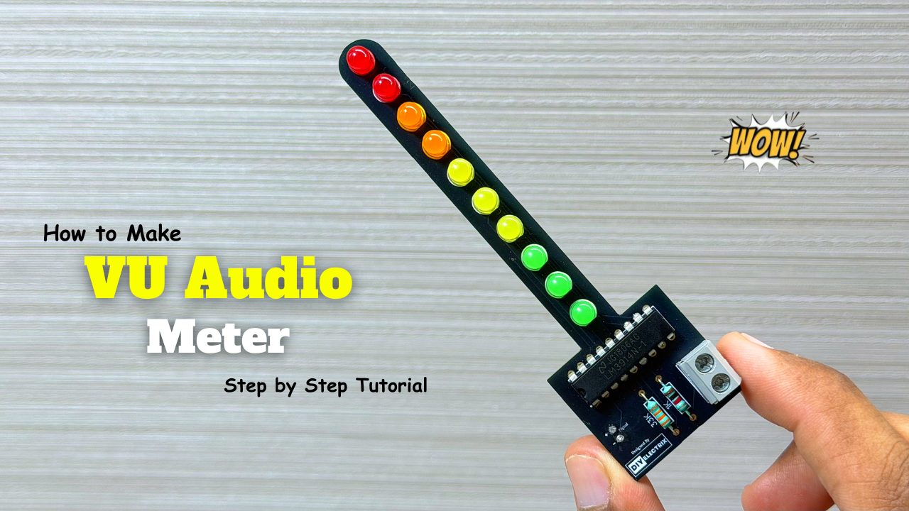
Audio Level Indicator – VU Meter
The VU meter—short for “volume unit meter”—is a device used to measure the average level of audio signals in terms of their loudness. It visually indicates the intensity of sound …
-
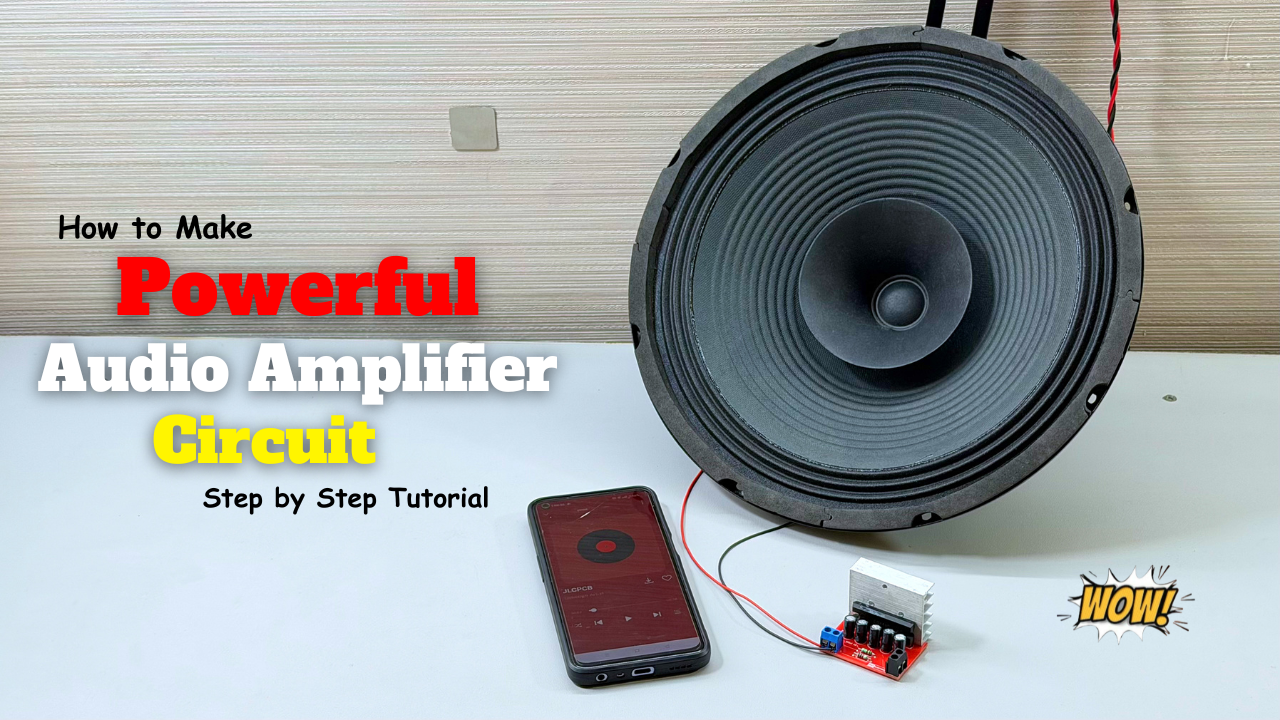
Powerful Audio Amplifier Using cd4440
Welcome to our latest video where we delve into the fascinating world of audio amplification using the CD4440 IC! In this comprehensive guide, we’ll walk you through the step-by-step process …
-
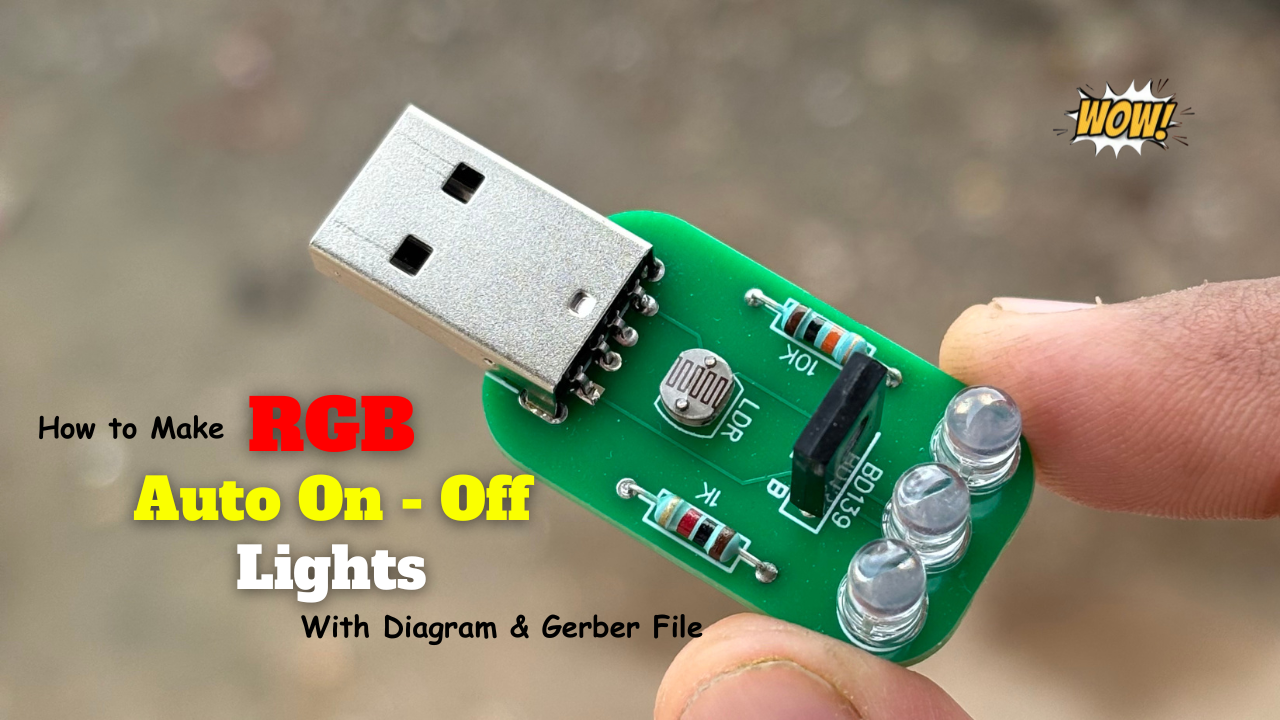
Building an Automatic Dark Sensor with BD139 Transistor
Light and darkness are two sides of the same coin, influencing our daily lives in ways we often overlook. Imagine a world where lights adjust themselves according to the ambient …