
An obstacle avoiding robot is a robotic vehicle designed to navigate its environment without colliding with obstacles. It uses sensors and microcontrollers to detect and avoid obstacles in its path. These robots are commonly used in automation, robotics education, and as introductory projects for learning about electronics and programming.
Components
- Arduino Uno
- Ultrasonic Sensor (e.g., HC-SR04)
- Servo Motor
- Motor Driver Module (e.g., L298N)
- DC Motors
- Battery Pack
- Switch
- Arduino IDE
Working Principle
- Sensor Data Collection:
- The ultrasonic sensor continuously measures the distance between the robot and obstacles.
- Decision Making:
- The Arduino Uno processes sensor input.
- If the distance to an obstacle is below a threshold, the Arduino triggers a response (e.g., stop, turn left/right).
- Actuation:
- Based on the decision, the motor driver controls the DC motors to move the car forward, turn, or reverse.
Steps to Build an Obstacle Avoiding Robot Car
- Assemble the Hardware:
- Mount the motors, ultrasonic sensor, and Arduino on the chassis.
- Connect the components as per the circuit diagram.
- Write the Code:
- Write or upload the obstacle avoiding code to the Arduino using the Arduino IDE.
- Use libraries like
NewPingfor ultrasonic sensors if needed.
- Upload and Test:
- Upload the code to the Arduino Uno.
- Test the robot to ensure it detects and avoids obstacles correctly.
Circuit Diagram
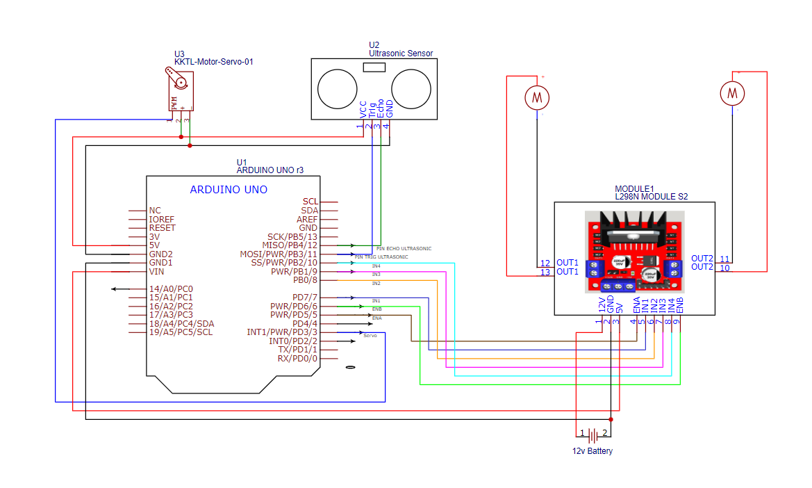
Connections
| Servo Motor | Pin 3 | Controls servo rotation. |
| Ultrasonic Trigger | Pin 11 | Emits ultrasonic pulses. |
| Ultrasonic Echo | Pin 12 | Receives reflected pulses. |
| Right Motor Enable | Pin 5 | Controls speed (PWM). |
| Right Motor Dir 1 | Pin 7 | Sets direction (Forward/Reverse). |
| Right Motor Dir 2 | Pin 8 | Sets direction (Forward/Reverse). |
| Left Motor Enable | Pin 6 | Controls speed (PWM). |
| Left Motor Dir 1 | Pin 9 | Sets direction (Forward/Reverse). |
| Left Motor Dir 2 | Pin 10 | Sets direction (Forward/Reverse). |
Code
#include <Servo.h>
#include <NewPing.h>

#define SERVO_PIN 3
#define ULTRASONIC_SENSOR_TRIG 11
#define ULTRASONIC_SENSOR_ECHO 12
#define MAX_REGULAR_MOTOR_SPEED 80
#define MAX_MOTOR_ADJUST_SPEED 170
#define DISTANCE_TO_CHECK 40

//Right motor
int enableRightMotor=5;
int rightMotorPin1=7;
int rightMotorPin2=8;

//Left motor
int enableLeftMotor=6;
int leftMotorPin1=9;
int leftMotorPin2=10;

NewPing mySensor(ULTRASONIC_SENSOR_TRIG, ULTRASONIC_SENSOR_ECHO, 400);
Servo myServo;
void setup()
{
  // put your setup code here, to run once:
  pinMode(enableRightMotor,OUTPUT);
  pinMode(rightMotorPin1,OUTPUT);
  pinMode(rightMotorPin2,OUTPUT);

  pinMode(enableLeftMotor,OUTPUT);
  pinMode(leftMotorPin1,OUTPUT);
  pinMode(leftMotorPin2,OUTPUT);

  myServo.attach(SERVO_PIN);
  myServo.write(90);
  rotateMotor(0,0);
}

void loop()
{

  int distance = mySensor.ping_cm();

  //If distance is within 30 cm then adjust motor direction as below
  if (distance > 0 && distance < DISTANCE_TO_CHECK)
  {
    //Stop motors
    rotateMotor(0, 0);
    delay(500);

    //Reverse motors
    rotateMotor(-MAX_MOTOR_ADJUST_SPEED, -MAX_MOTOR_ADJUST_SPEED);
    delay(200);

    //Stop motors
    rotateMotor(0, 0);
    delay(500);

    //Rotate servo to left
    myServo.write(180);
    delay(500);

    //Read left side distance using ultrasonic sensor
    int distanceLeft = mySensor.ping_cm();

    //Rotate servo to right
    myServo.write(0);
    delay(500);

    //Read right side distance using ultrasonic sensor
    int distanceRight = mySensor.ping_cm();

    //Bring servo to center
    myServo.write(90);
    delay(500);

    if (distanceLeft == 0 )
    {
      rotateMotor(MAX_MOTOR_ADJUST_SPEED, -MAX_MOTOR_ADJUST_SPEED);
      delay(550);
    }
    else if (distanceRight == 0 )
    {
      rotateMotor(-MAX_MOTOR_ADJUST_SPEED, MAX_MOTOR_ADJUST_SPEED);
      delay(550);
    }
    else if (distanceLeft >= distanceRight)
    {
      rotateMotor(MAX_MOTOR_ADJUST_SPEED, -MAX_MOTOR_ADJUST_SPEED);
      delay(550);
    }
    else
    {
      rotateMotor(-MAX_MOTOR_ADJUST_SPEED, MAX_MOTOR_ADJUST_SPEED);
      delay(550);
    }
    rotateMotor(0, 0);
    delay(550);
  }
  else
  {
    rotateMotor(MAX_REGULAR_MOTOR_SPEED, MAX_REGULAR_MOTOR_SPEED);
  }
}


void rotateMotor(int rightMotorSpeed, int leftMotorSpeed)
{
  if (rightMotorSpeed < 0)
  {
    digitalWrite(rightMotorPin1,LOW);
    digitalWrite(rightMotorPin2,HIGH);
  }
  else if (rightMotorSpeed >= 0)
  {
    digitalWrite(rightMotorPin1,HIGH);
    digitalWrite(rightMotorPin2,LOW);
  }

  if (leftMotorSpeed < 0)
  {
    digitalWrite(leftMotorPin1,LOW);
    digitalWrite(leftMotorPin2,HIGH);
  }
  else if (leftMotorSpeed >= 0)
  {
    digitalWrite(leftMotorPin1,HIGH);
    digitalWrite(leftMotorPin2,LOW);
  }

  analogWrite(enableRightMotor, abs(rightMotorSpeed));
  analogWrite(enableLeftMotor, abs(leftMotorSpeed));
}
Applications
- Automation:
- Useful in factories and warehouses for autonomous navigation.
- Education:
- A great project for learning robotics and Arduino programming.
- Hobbyist Projects:
- Popular among robotics enthusiasts for DIY projects.
- Research:
- Basis for advanced navigation and AI-based robots.
Arduino Uno:
At its core, the Arduino Uno is a microcontroller board based on the ATmega328P chip. The microcontroller is essentially a tiny computer that can read inputs (like sensors or switches), process those inputs, and control outputs (like LEDs, motors, or screens). It is a part of the Arduino ecosystem, which consists of hardware and software that make it easy for anyone to create interactive electronic projects.
The Arduino Uno is an open-source platform, meaning its design is freely available for modification and distribution. This openness has led to a global community of makers and developers who share their knowledge, code, and project ideas, contributing to the growing popularity of the Arduino platform.
Key Features of the Arduino Uno
The Arduino Uno is designed with simplicity and ease of use in mind. Some of the key features that make it a great choice for beginners include:
- Microcontroller: The Arduino Uno is powered by the ATmega328P microcontroller, which has 32KB of flash memory and 2KB of SRAM, making it capable of handling a wide variety of projects.
- Digital I/O Pins: The board has 14 digital I/O pins, which can be used for reading digital signals (HIGH or LOW). Out of these, 6 pins can also be used as PWM (pulse-width modulation) outputs to control things like motor speed or LED brightness.
- Analog Input Pins: The board features 6 analog input pins, which allow it to read varying voltages (like sensor outputs). These can be used to interface with analog devices such as temperature sensors or potentiometers.
- USB Connection: The Arduino Uno connects to your computer through a USB port, making it easy to upload code and communicate with the board. You can also power the board via USB.
- Power Options: In addition to USB power, the Arduino Uno can also be powered via an external 9V battery or power supply. It includes a voltage regulator to ensure stable operation.
- Built-in LED: The board comes with a built-in LED on pin 13, which is useful for simple debugging and testing your code.
- Arduino IDE Compatibility: The Arduino Uno works seamlessly with the Arduino IDE (Integrated Development Environment), a free software that you can use to write and upload your code. The IDE is beginner-friendly, with a simple interface that allows you to write, compile, and upload your code to the board.
More Project
-
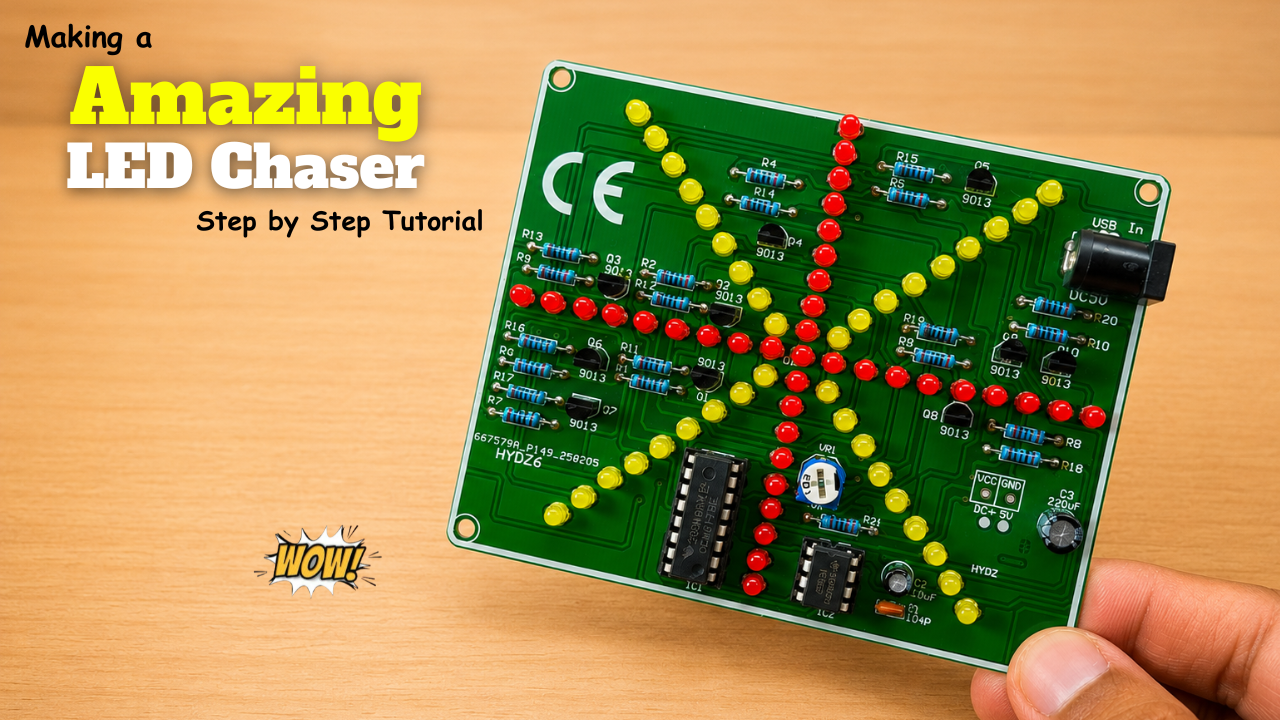
Making a Amazing LED Chaser Circuit!
LED chasers are a fun and creative way to display a sequence of lights. In this blog post, we’ll show you how to build an LED chaser using a 555 …
-
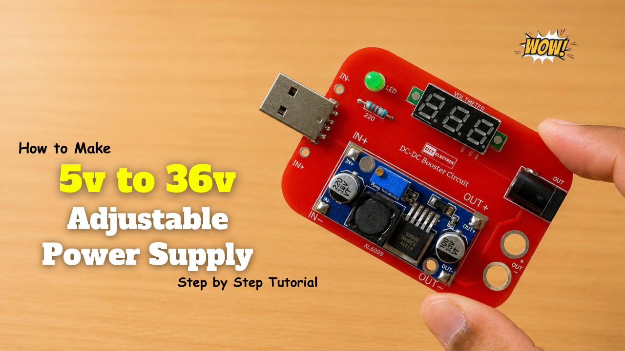
Making a 5V-to-36V Adjustable Power Supply Circuit!
Build a versatile adjustable DC power supply that converts a fixed input voltage into a variable output ranging from 5V to 36V using a DC-DC boost converter. The output voltage …
-
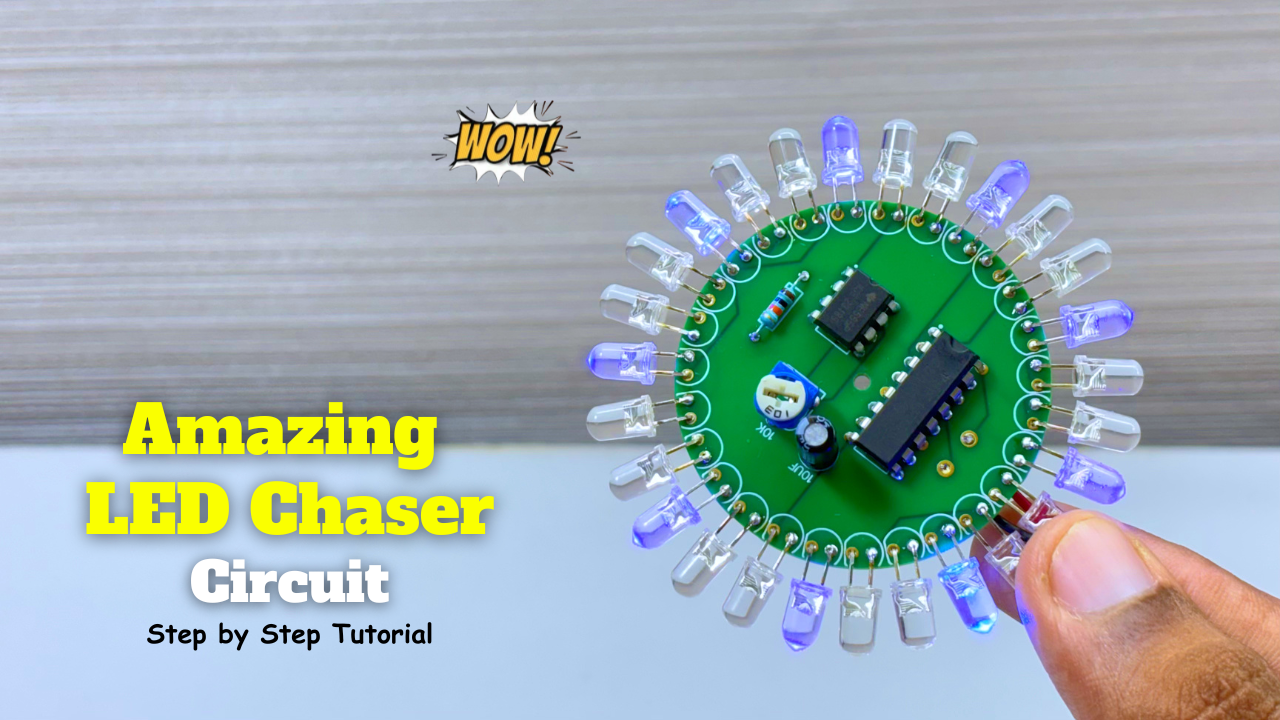
Amazing LED Chaser Circuit – Beautiful Decoration Idea
LED chasers are a fun and creative way to display a sequence of lights. In this blog post, we’ll show you how to build an LED chaser using a 555 …