
A Dimmer is an electronic device that uses PWM signals to control the speed and direction of a motor. It works by varying the width of the pulses to adjust the average voltage applied to the motor, thereby controlling its speed.
Advantages:
- High efficiency
- Smooth speed control
- Low heat generation
- Simple implementation
Applications:
- DC motor speed control
- Stepper motor control
- Brushless DC motor control
- Robotics
- CNC machines
- Electric vehicles
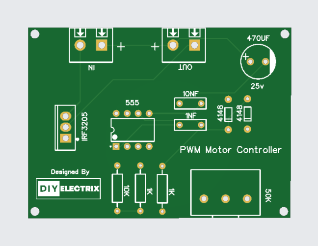
Components Used:
- Irf3205 Mosfet
- 555 Timer Ic
- 4148 Diode * 2
- 10k Ohm resistor
- 1k Ohm resistor * 2
- 0.01uf capacitor
- 0.1uf capacitor
- 470uf
- 10k Potentiometer
- Connectors
- 12v power Supply
Gerber File:
Special Thanks to Our Sponser – JLCPCB:
No project is complete without the right tool and materials. That’s why our sponser JLCPCB stepped into provide essential material for the project. JLCPCB is a leading provider of high quality printed circuit board and PCB assembling services.
Simply head over to JLCPCB, Upload your gerber file, select specification and just place your order.
48-Hour Turnaround for 6 Layer PCBs!

Discover Easy, Affordable, and Reliable PCB manufacturing with JLCPCB! Register to get $60 New customer coupons.

How To Order PCB
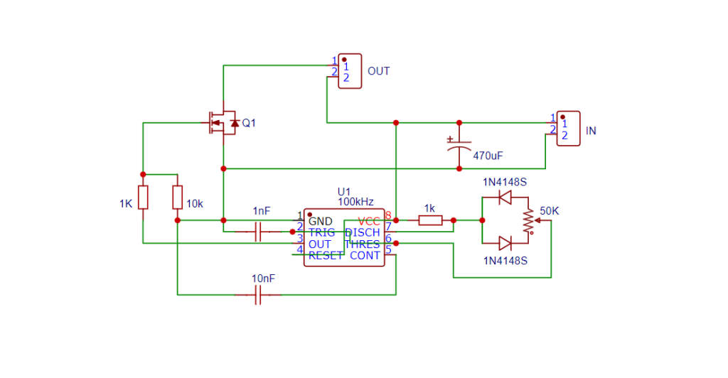
Circuit Diagram:
Irf3205 MOSFET:
IFR3205 MOSFET: A Powerhouse for Your Electronics Projects
The IFR3205 MOSFET is a high-power, high-speed switching device that has become a staple in many electronics projects. Its impressive performance and reliability make it an ideal choice for a wide range of applications, from power supplies to motor control circuits.
Pinout:
The IFR3205 MOSFET has three pins:
- Gate (G): Pin 1
- Drain (D): Pin 2
- Source (S): Pin 3
Features:
- High current rating: 110A
- High voltage rating: 55V
- Low on-resistance: 8.5mΩ
- Fast switching times: 15ns rise, 30ns fall
- High thermal performance: 200°C junction temperature
Applications:
- Power supplies
- Motor control circuits
- Switching regulators
- Audio amplifiers
- High-power LED drivers
How to Use:
- Connect the gate pin to your control signal (e.g., PWM, logic level).
- Connect the drain pin to your load (e.g., motor, LED).
- Connect the source pin to ground.
- Ensure proper heat sinking for high-power applications.
Conclusion:
The IFR3205 MOSFET is a powerful and versatile device that can handle demanding applications with ease. Its impressive performance, reliability, and affordability make it a popular choice among electronics enthusiasts and professionals alike.
555 Timer IC:
The 555 timer IC is a legendary integrated circuit that has been a cornerstone of electronics projects for decades. Introduced in 1972 by Signetics, this versatile chip has become a staple in the world of electronics, renowned for its simplicity, reliability, and flexibility. The 555 timer IC is a monolithic timing circuit that can be used in a wide range of applications, including oscillators, timers, pulse generators, and alarm circuits. It consists of two main components: a voltage-controlled oscillator (VCO) and a flip-flop. The VCO generates a square wave output, while the flip-flop acts as a Schmitt trigger, providing hysteresis and ensuring clean switching.
Pinout and Configuration:
The 555 timer IC has eight pins, each with a specific function:
- Pin 1: Ground
- Pin 2: Trigger input
- Pin 3: Output
- Pin 4: Reset input
- Pin 5: Control voltage input
- Pin 6: Threshold input
- Pin 7: Discharge pin
- Pin 8: Supply voltage (Vcc)
The 555 can be configured in various modes, including:
- Monostable (one-shot) mode
- Astable (free-running) mode
- Bistable (Schmitt trigger) mode
Applications and Projects:
The 555 timer IC has been used in countless projects, including:
- Timer circuits (e.g., egg timers, alarm systems)
- Oscillators (e.g., audio signals, LED flashers)
- Pulse generators (e.g., infrared transmitters, ultrasonic cleaners)
- Alarm circuits (e.g., motion detectors, smoke detectors)
- LED flashers and blinkers
- Audio circuits (e.g., tone generators, sound effects)
More Projects
-
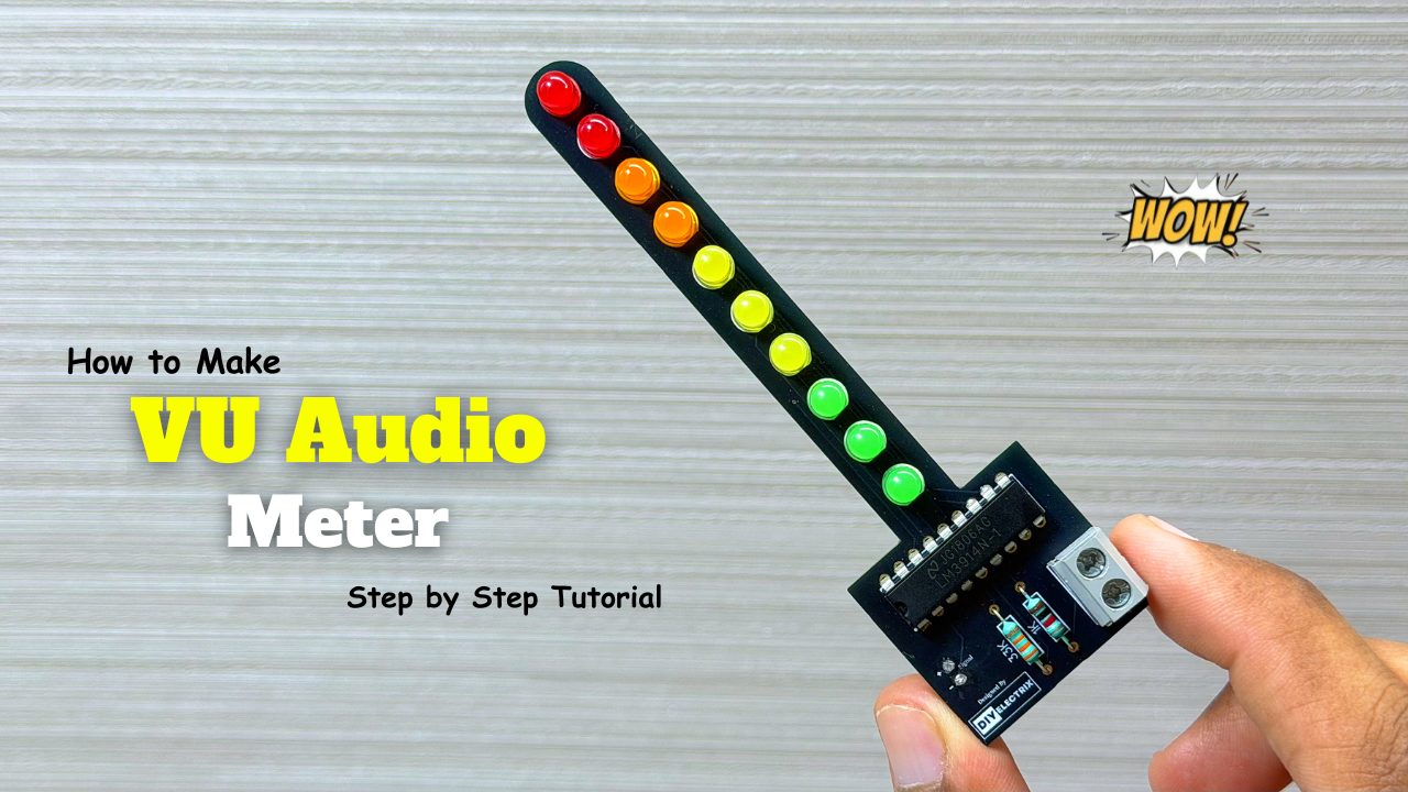
Audio Level Indicator – VU Meter
The VU meter—short for “volume unit meter”—is a device used to measure the average level of audio signals in terms of their loudness. It visually indicates the intensity of sound …
-
Powerful Audio Amplifier Using cd4440
Welcome to our latest video where we delve into the fascinating world of audio amplification using the CD4440 IC! In this comprehensive guide, we’ll walk you through the step-by-step process …
-
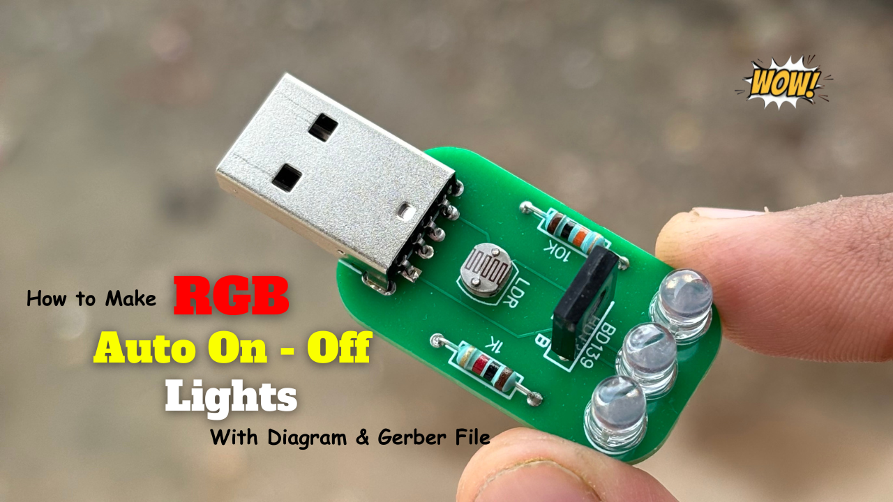
Building an Automatic Dark Sensor with BD139 Transistor
Light and darkness are two sides of the same coin, influencing our daily lives in ways we often overlook. Imagine a world where lights adjust themselves according to the ambient …