The VU meter—short for “volume unit meter”—is a device used to measure the average level of audio signals in terms of their loudness. It visually indicates the intensity of sound in decibels (dB) on a scale, providing real-time feedback to audio engineers, producers, and anyone involved in the audio process.
The classic VU meter looks like a moving needle on a dial, often with a scale ranging from -20 to +3 dB (with 0 dB representing the “0 VU” reference point). Some modern digital VU meters use a digital bar graph display, but the principle remains the same: the VU meter’s primary purpose is to show how loud the audio is at any given moment.
How it Works:
LED VU meters work based on the same principle as traditional analog VU meters: they measure the average loudness of an audio signal over time, providing a visual representation of how strong the signal is. However, instead of using a moving needle, LED meters use multiple LEDs (usually red, yellow, or green) arranged in a row.
Components Required:
- LM3914 IC
- LED
- 1k & 33k Ohm Resistor
- Amplifier circuit
- Connector
Applications:
LED VU meters are widely used in various audio applications, including:
- Audio Recording and Mixing: In recording studios, LED VU meters are used on mixing consoles, audio interfaces, and recording software to monitor and control the levels of the audio being processed.
- Live Sound Systems: For live sound engineers, LED VU meters are essential for ensuring proper signal levels, preventing distortion, and balancing the mix during a performance.
- Broadcasting: Radio and TV stations use LED VU meters to maintain consistent audio levels during broadcasts, ensuring that sound is clear and within acceptable levels.
- Home Audio Systems: Many modern home stereo systems and audio receivers come with built-in LED VU meters, allowing users to visually monitor their audio levels while listening to music.
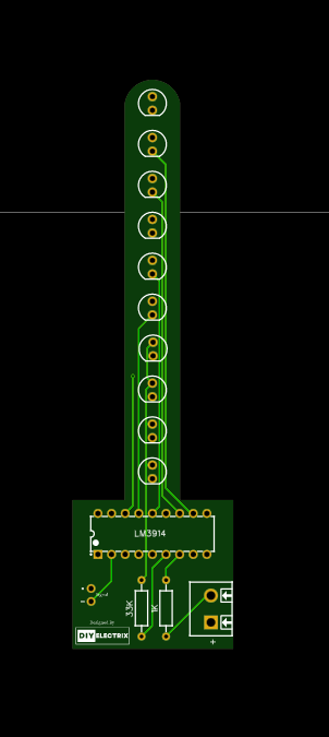
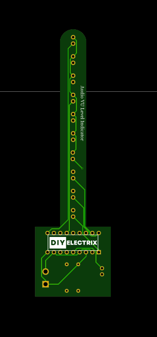
Gerber File:


Special Thanks to Our Sponser – JLCPCB:
No project is complete without the right tool and materials. That’s why our sponser JLCPCB stepped into provide essential material for the project. JLCPCB is a leading provider of high quality printed circuit board and PCB assembling services.
Simply head over to JLCPCB, Upload your gerber file, select specification and just place your order.
JLCPCB PCB Fab & Assembly from $2! Sign up to Get $80 Coupons

Sign Up to Get $80 New User Coupons.

How To Order PCB
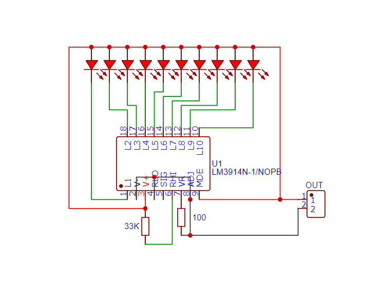
Circuit Diagram:

LM3914 IC:
The LM3914 is a voltage level indicator IC that can drive an array of LEDs in a bar graph or LED display configuration. The IC provides a linear response, meaning the LED brightness or number of lit segments increases in direct proportion to the input voltage. The LM3914 is designed to operate with a single power supply and is optimized for driving LEDs with minimal external components.
Key features of the LM3914 include:
- 10-step LED driver: It can control up to 10 LEDs to display a range of values.
- Linear output: The LED array lights up in a smooth, linear progression as the input voltage increases.
- Low power consumption: The LM3914 is designed to work efficiently, consuming minimal power when driving the LEDs.
- Selectable display modes: You can configure the LM3914 to display the input signal in bar graph mode (where multiple LEDs light up gradually) or LED display mode (where only one LED lights up at a time).
- Internal reference voltage: The IC has an internal voltage reference, making it simple to set up without the need for external reference circuitry.
How Does the LM3914 Work?
The LM3914 operates by comparing an input voltage (V_in) to a reference voltage (V_ref) and lighting up a series of LEDs in proportion to the input voltage level. The IC divides the input voltage range into 10 equal steps, lighting one LED for each step.
- LED Bar Graph Mode: In this mode, the LEDs light up sequentially from left to right as the input voltage increases.
- LED Display Mode: Here, only the highest LED corresponding to the input voltage level lights up. This mode provides a “step-by-step” display, where only one LED is on at a time.
To get started, you would connect the input signal (for example, an audio signal or voltage to monitor) to the LM3914’s input pin (pin 5). The IC then compares this voltage to an internally set reference, lighting the appropriate number of LEDs.
Pinout of the LM3914
The LM3914 is a 10-pin IC. Here’s the pinout for the LM3914:
- Pin 1 (REF OUT): Output of internal voltage reference.
- Pin 2 (Ref Adj): Pin for adjusting the reference voltage.
- Pin 3 (V–): Negative power supply connection.
- Pin 4 (Pin 9 of LED Display): Control pin for LED output (base of transistor).
- Pin 5 (V_in): Input voltage to be displayed.
- Pin 6 (Display Mode Control): Mode control (bar graph or LED display).
- Pin 7 (LED cathode): Negative side of LEDs.
- Pin 8 (V+): Positive power supply.
- Pin 9 (LED Anode): Positive side of LEDs.
- Pin 10 (LED Anode): Additional LED pin or output.
The IC takes the voltage at the input pin (Pin 5) and compares it to an internal reference voltage. The number of LEDs that light up depends on the relative value of the input voltage to the reference.
LM3914 Applications
The LM3914 is versatile and can be used in a variety of applications where a visual representation of an analog signal is needed. Some of the most common uses include:
- Audio Level Indicators (VU Meters):
The LM3914 is often used in audio applications to create LED VU meters, where the input is the audio signal, and the LEDs represent the loudness of the audio in real-time. This is especially popular in mixing consoles, home audio systems, and sound equipment. - Battery Level Indicators:
It can be used in battery-powered devices to show the charge level of a battery. As the battery discharges, fewer LEDs will light up, indicating the remaining power. - Temperature Indicators:
In conjunction with a temperature-to-voltage conversion circuit (e.g., a thermistor or thermocouple), the LM3914 can be used to display the temperature with a corresponding LED readout. - Voltage Level Indicator:
You can use the LM3914 to monitor the voltage in a circuit. As the voltage increases or decreases, the LEDs will show a visual representation of the voltage level. - Signal Strength Indicators:
The LM3914 can be used in communication systems to show the strength of a radio or other signal. This is particularly useful in radio transmitters, receivers, and monitoring equipment. - Audio Visualizers and Light Effects:
In creative applications, the LM3914 can be used to create visual effects, such as synchronized LED displays in audio visualizers, light shows, or interactive art installations.
Advantages of the LM3914
- Simple to Use: The LM3914 requires very few external components to get started. It simplifies the process of building LED level indicators.
- Low Power Consumption: The IC is designed to be power-efficient, making it suitable for battery-powered projects.
- Versatile: The IC can drive up to 10 LEDs, and you can cascade multiple ICs to drive more LEDs if needed.
- Adjustable Reference Voltage: You can adjust the reference voltage (with the REF ADJ pin) to change the range of input voltages that the IC can display.
- Easy Mode Switching: You can easily switch between bar graph and LED display modes, depending on how you want to visualize the input signal.
-
Building an Automatic Dark Sensor with BD139 Transistor

Light and darkness are two sides of the same coin, influencing our daily lives in ways we often overlook. Imagine a world where lights adjust themselves according to the ambient …
-
Safely Assembling 24V 100Ah Battery Pack – Step by Step!

Building an 8S (8 series) LiFePO4 battery pack using LiFePO4 cells and a Daly Battery Management System (BMS). If you’re planning your own DIY power storage project, this guide might …
-
How to Make 3.7v Li-ion Battery Charger

A 3.7 V lithium-ion charger using LM358 is a classic DIY solution and great for learning battery charging fundamentals. Below is a clear, practical explanation + working concept. Charging a …
