
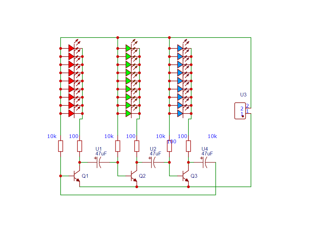
An LED chaser is an electronic circuit that lights LEDs one after another in a sequence. It creates a running or chasing light effect commonly seen in decorations and indicators.
Components Required:
- BC507 Transistor
- 12v Relay
- 1k ohm
- 15k ohm
- 1N4007 Diode
- 5408 Diode
- LED – green & red
- Potentiometer 10k (103)
- Connector
- 14V Power supply
Circuit Diagram:
Special Thanks to Our Sponser – JLCPCB:
No project is complete without the right tool and materials. That’s why our sponser JLCPCB stepped into provide essential material for the project. JLCPCB is a leading provider of high quality printed circuit board and PCB assembling services.
Simply head over to JLCPCB, Upload your gerber file, select specification and just place your order.
48-Hour Turnaround for 6 Layer PCBs!

$0 for 2u” ENIG. Free Via-in-Pad. High Precision. Sign Up to Get $80 New User Coupons.

How To Order PCB
BC547 Transistor
The BC547 is a general-purpose NPN transistor made from silicon. It is mainly used where small signals need to be amplified or controlled. Because of its low cost, reliability, and availability, it is one of the most popular transistors in the world.
Basic Information
| Parameter | Value |
|---|---|
| Type | NPN BJT |
| Package | TO-92 |
| Material | Silicon |
| Operation | Amplifier / Switch |
| Polarity | NPN |
Pin Configuration (TO-92)
When the flat side faces you and the legs point downward:
Base (B) – Control terminal
- Emitter (E) – Current exits
⚠️ Pin order may vary slightly by manufacturer, so always check the datasheet.
⚙️ Working Principle
The BC547 works on the principle of current amplification.
🔹 Basic Rule
A small current at the Base controls a large current between Collector and Emitter.
🟢 Switch Mode
- Base current = OFF → No C-E current
- Base current = ON → C-E current flows
Used for:
- LED ON/OFF control
- Relay driving (small relays)
- Digital switching
🔵 Amplifier Mode
- Weak AC signal applied at base
- Strong amplified signal obtained at collector
Used in:
- Audio amplifiers
- Microphone circuits
- Sensor signal amplification
📊 Electrical Characteristics
| Parameter | Typical Value |
|---|---|
| Vceo (Max Collector-Emitter Voltage) | 45 V |
| Ic max (Collector Current) | 100 mA |
| hFE (Current Gain) | 110 – 800 |
| Power Dissipation | 500 mW |
| Transition Frequency (ft) | ~300 MHz |
🔈 Gain Classification
BC547 comes in three gain versions:
| Type | Gain (hFE) |
|---|---|
| BC547A | 110 – 220 |
| BC547B | 200 – 450 |
| BC547C | 420 – 800 |
✔ Higher gain = better amplification
🧪 Applications of BC547
✔ Audio pre-amplifiers
✔ Signal amplifiers
✔ Microcontroller interfacing
✔ Relay driver circuits
✔ Light & temperature sensors
✔ FM transmitter circuits
✔ Logic switching circuits
🔄 BC547 vs Similar Transistors
| Transistor | Type | Notes |
|---|---|---|
| BC547 | NPN | Low noise, general purpose |
| BC548 | NPN | Lower noise than BC547 |
| BC549 | NPN | Ultra-low noise |
| 2N3904 | NPN | American equivalent |
| C1815 | NPN | Audio applications |
⚠️ Important Notes
- Do not exceed 100 mA current
- Use base resistor to protect transistor
- Suitable only for low-power circuits
- Not recommended for high-current loads (motors)
How relay works
A relay is an electrically operated switch that uses an electromagnet to control a separate electrical circuit. When a small current flows through the relay’s coil, it creates a magnetic field that pulls a metal armature, causing the relay contacts to change their position. This action can close (NO – Normally Open) or open (NC – Normally Closed) a circuit, allowing a low-power signal to safely control a high-voltage or high-current load. When the coil current is switched off, the magnetic field collapses and a spring returns the contacts to their original state. Relays provide electrical isolation, protect control circuits, and are widely used in automation, motor control, and electronic systems.
More Projects
-
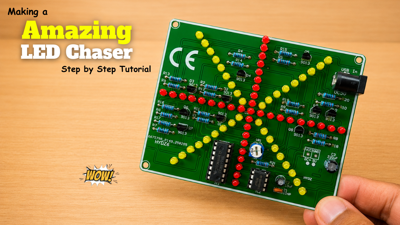
Making a Amazing LED Chaser Circuit!
LED chasers are a fun and creative way to display a sequence of lights. In this blog post, we’ll show you how to build an LED chaser using a 555 …
-
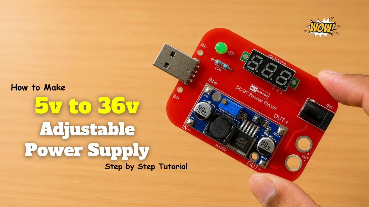
Making a 5V-to-36V Adjustable Power Supply Circuit!
Build a versatile adjustable DC power supply that converts a fixed input voltage into a variable output ranging from 5V to 36V using a DC-DC boost converter. The output voltage …
-
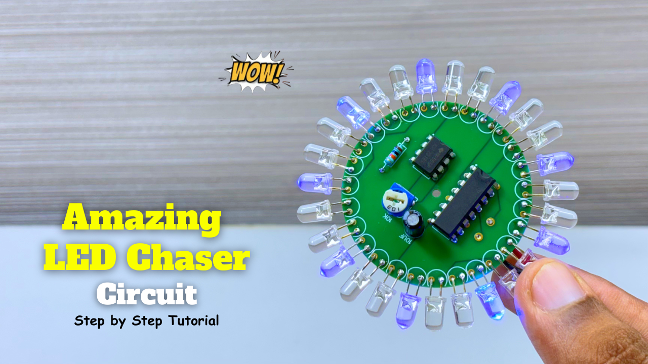
Amazing LED Chaser Circuit – Beautiful Decoration Idea
LED chasers are a fun and creative way to display a sequence of lights. In this blog post, we’ll show you how to build an LED chaser using a 555 …