
Proximity sensors are widely used in automation, security, and robotics to detect the presence of nearby objects without physical contact. While modern sensors use complex ICs or microcontrollers, you can build a basic proximity sensor circuit using a BC547 transistor and a few simple components.
This DIY project is perfect for beginners to understand the working principle of object detection using infrared light and transistors.
Components Required
- BC547 NPN transistor – 1x
- IR LED (Infrared Transmitter) – 1x
- Photodiode or IR Receiver LED – 1x
- LED (Indicator) – 1x
- Resistors – 47k, 100 ohm
- Power Supply – 12v
- Buzzer
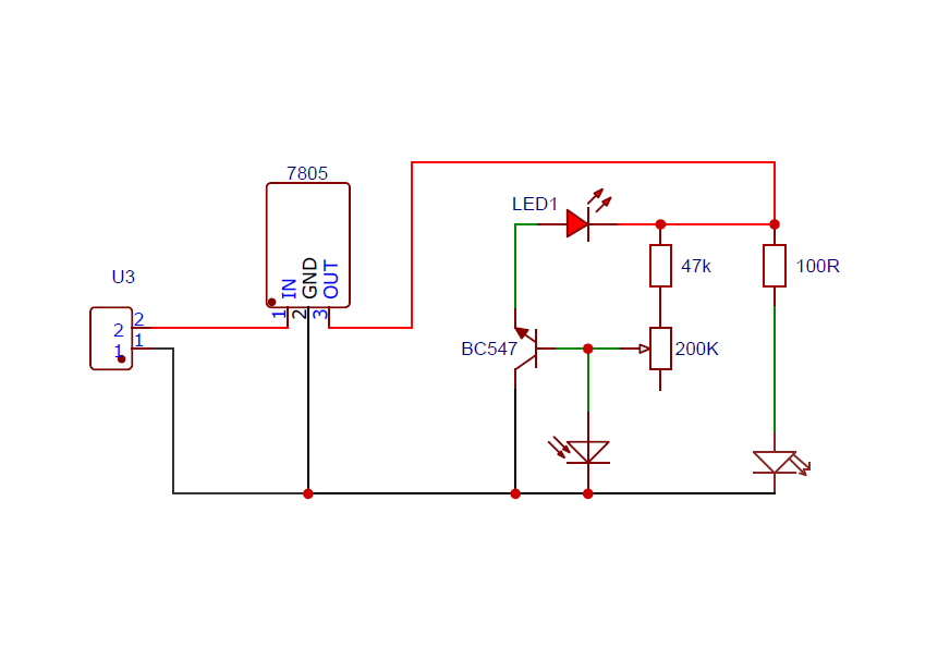
Working Explanation
Let’s break down the operation step-by-step:
- The IR LED emits light that is invisible to the naked eye.
- In normal conditions, the IR receiver receives little to no reflected IR light.
- When an object (like a hand) comes near, IR light reflects off it and hits the receiver.
- The photodiode produces a small voltage when IR is detected.
- This voltage is fed to the base of the BC547 via a current-limiting resistor.
- Once the base voltage exceeds the threshold (~0.7V), the transistor conducts.
- The collector-emitter path allows current to flow and turns ON the LED.
You’ve just created a simple object detection sensor using basic components!
Special Thanks to Our Sponser – JLCPCB:
No project is complete without the right tool and materials. That’s why our sponser JLCPCB stepped into provide essential material for the project. JLCPCB is a leading provider of high quality printed circuit board and PCB assembling services.
Simply head over to JLCPCB, Upload your gerber file, select specification and just place your order.
48-Hour Turnaround for 6 Layer PCBs!

Discover Easy, Affordable, and Reliable PCB manufacturing with JLCPCB! Register to get $60 New customer coupons.

How To Order PCB
Circuit Diagram:
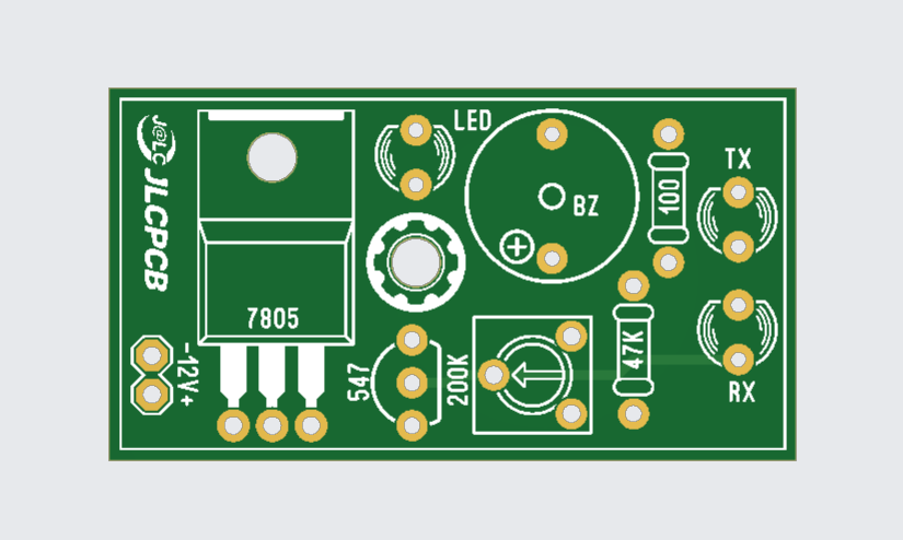
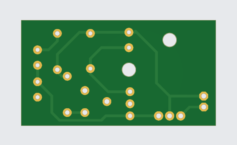
Gerber File:
Applications
- Automatic hand sanitizer dispensers
- Obstacle detection in robots
- Touchless switches
- Security systems
BC547 Transistor:
The BC547 is one of the most popular and widely used NPN bipolar junction transistors (BJT). It’s commonly found in hobby electronics, educational kits, and low-power electronic circuits.
Basic Specifications
| Parameter | Value |
|---|---|
| Transistor Type | NPN |
| Max Collector Current (Ic) | 100 mA |
| Max Collector-Emitter Voltage (Vce) | 45 V |
| Max Collector-Base Voltage (Vcb) | 50 V |
| Max Emitter-Base Voltage (Veb) | 6 V |
| DC Current Gain (hFE) | 110 to 800 |
| Package Type | TO-92 |
| Power Dissipation | ~500 mW |
| Transition Frequency (ft) | ~150 MHz |
Pin Configuration (TO-92 Package)
- Collector
- Base
- Emitter
How It Works
The BC547 acts like an electronic switch or amplifier. It operates in three main regions:
- Cut-off Region – Both junctions are reverse-biased → Transistor OFF
- Active Region – Base-emitter junction is forward-biased → Amplifies current
- Saturation Region – Both junctions are forward-biased → Transistor ON (switching mode)
To turn the transistor ON, you apply a small current (usually through a resistor) to the base, which allows a larger current to flow from the collector to emitter.
Common Uses
- Switching circuits (turning on LEDs, relays, etc.)
- Signal amplification (audio preamps, small signal amps)
- Sensor interfacing (e.g., IR, LDR, temperature sensors)
- Oscillator circuits
- Transistor-based logic gates
Example Applications
- LED flasher circuit
- IR proximity sensor (like the one we discussed)
- Audio amplifier input stage
- BC547 + 555 Timer based circuits
Why Use BC547?
- Readily available and inexpensive
- Ideal for low-power circuits
- Easy to use in breadboard and perfboard setups
- Works well with 5V and 9V systems (e.g., Arduino, battery-based projects)
Important Notes
- Do not exceed 100 mA collector current, or you risk damaging the transistor.
- Always use a base resistor (typically 1kΩ–10kΩ) to limit base current.
- For higher current switching, use power transistors like TIP122 or MOSFETs.
Quick Test (Using Multimeter)
To check if your BC547 is working:
- Set multimeter to diode mode
- Connect red lead to base, black to collector → You should see ~0.6V
- Red to base, black to emitter → ~0.6V
- Any other combination → no conduction