
Creating a DIY Electronic Piano using a 555 Timer IC is a fun and educational electronics project. It teaches you about sound generation using a basic timer circuit. Here’s a complete guide to help you build one.
Components Required:
- 555 Timer IC
- 0.5W 8ohm Speaker
- 1kΩ
- 2kΩ
- 0.1uf Capacitor
- 4.7 uf capacitor
- WIre
- 9v Battery & Cap
- Connector
Special Thanks to Our Sponser – JLCPCB:
No project is complete without the right tool and materials. That’s why our sponser JLCPCB stepped into provide essential material for the project. JLCPCB is a leading provider of high quality printed circuit board and PCB assembling services.
Simply head over to JLCPCB, Upload your gerber file, select specification and just place your order.
48-Hour Turnaround for 6 Layer PCBs!
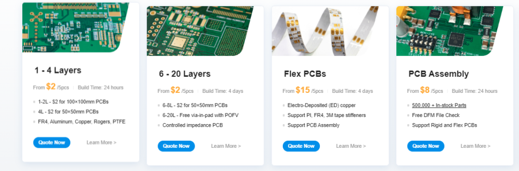
$0 for 2u” ENIG. Free Via-in-Pad. High Precision. Sign Up to Get $80 New User Coupons.
How To Order PCB
Working Principle
The 555 Timer IC is configured in Astable mode, where it continuously oscillates between high and low outputs, generating a square wave. The frequency of this square wave determines the pitch of the sound produced — like different musical notes.
Frequency Formula (Astable Mode):
f=1.44(R1+2R2)⋅Cf = \frac{1.44}{(R1 + 2R2) \cdot C}f=(R1+2R2)⋅C1.44
So, by changing R1, R2, or C, you change the frequency of the output sound.
How the Piano Works
- Each push button is wired with different resistor values in series (or different capacitor values).
- Pressing a button completes the circuit and connects a unique resistor (or capacitor) to the 555 timer.
- This changes the RC time constant, which changes the output frequency of the 555 timer.
- The output goes to a speaker, producing a tone corresponding to the frequency.
- Each button gives you a different note — forming a basic piano!
Example:
- Button 1: 1kΩ resistor → high frequency → high-pitched tone (e.g., Note C)
- Button 2: 2.2kΩ resistor → slightly lower frequency → lower tone (e.g., Note D)
What is a 555 Timer IC?
The 555 Timer IC is a popular and widely used integrated circuit designed for timing, pulse generation, and oscillator applications. It was first introduced in 1972 by Signetics and has since become a fundamental component in electronics projects.
It can be configured in three main modes:
- Monostable Mode – acts as a one-shot timer.
- Astable Mode – generates a continuous square wave (used in sound generation, blinking LEDs, etc.).
- Bistable Mode – acts as a flip-flop or memory element.
Key Features:
- Operates from 4.5V to 15V power supply.
- Can source or sink up to 200mA of current.
- Has a high output drive capability.
- Easy to use with minimal external components.
Common Applications:
- Sound generation (as in electronic pianos)
- LED flashers/blinkers
- Timers and delays
- Pulse-width modulation (PWM)
- Frequency generators
- Oscillators
Why It’s Used in an Electronic Piano:
In an electronic piano project, the 555 timer is used in astable mode to produce different frequencies of sound. By pressing different keys (buttons) connected with different resistors, the timer’s frequency changes, creating different musical tones when the output is fed to a speaker.
-
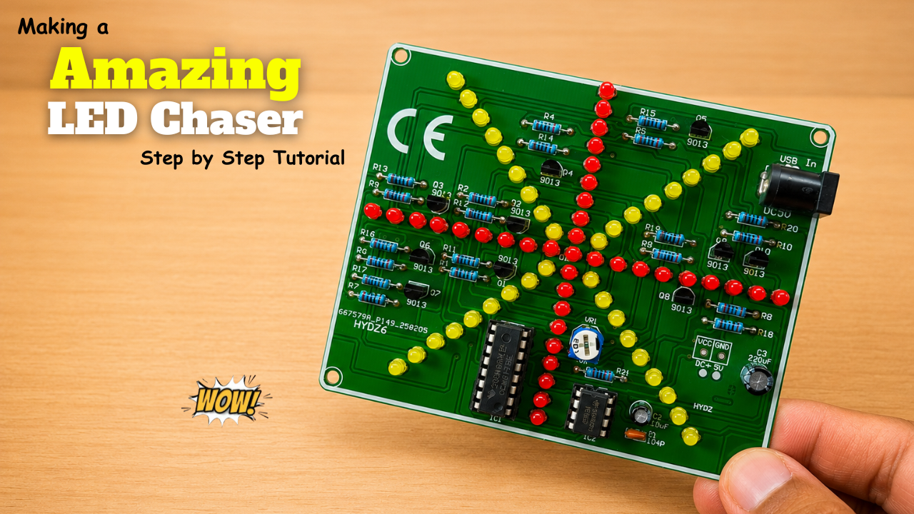
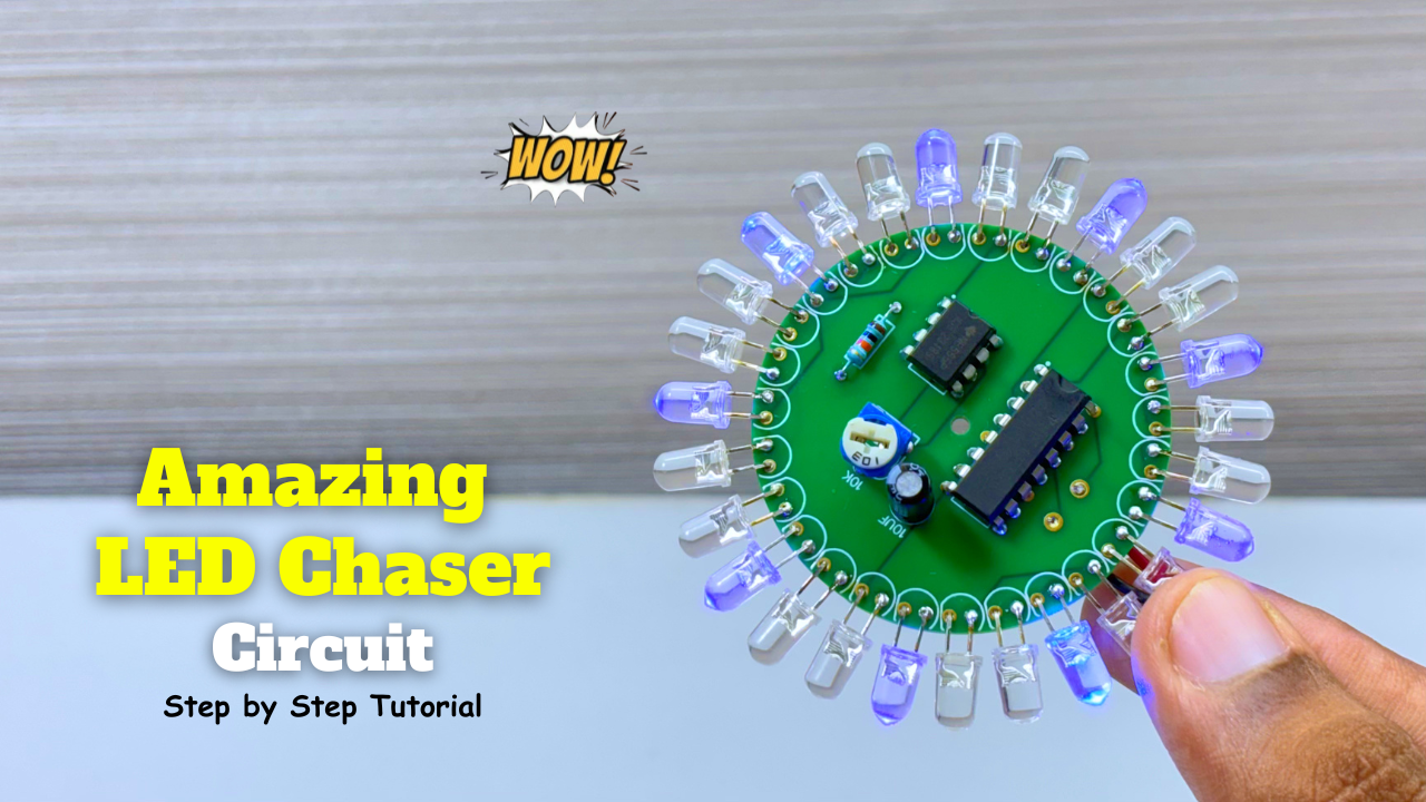
Making a Amazing LED Chaser Circuit!
LED chasers are a fun and creative way to display a sequence of lights. In this blog post, we’ll show you how to build an LED chaser using a 555 …
-
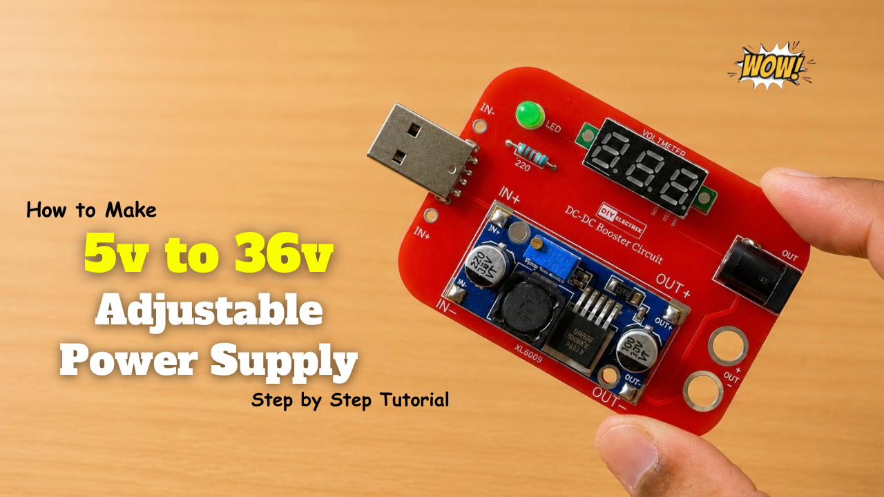
Making a 5V-to-36V Adjustable Power Supply Circuit!
Build a versatile adjustable DC power supply that converts a fixed input voltage into a variable output ranging from 5V to 36V using a DC-DC boost converter. The output voltage …
-
Amazing LED Chaser Circuit – Beautiful Decoration Idea
LED chasers are a fun and creative way to display a sequence of lights. In this blog post, we’ll show you how to build an LED chaser using a 555 …