
A servo motor controller circuit is an electronic system designed to control the position, speed, and direction of a servo motor. Servo motors are used in various applications, including robotics, automation, and precision control systems. The controller circuit typically receives control signals (often from a microcontroller or external controller) and adjusts the servo motor’s movement accordingly.
Applications of Servo Motor Controller Circuits
- Robotics: For controlling robotic arms, legs, and other movements.
- CNC Machines: To precisely position parts.
- RC Vehicles: For controlling steering and throttle.
- Industrial Automation: To control the positioning of machinery.
- Antenna Positioning: To orient satellite dishes or radio antennas.
Components Required:
- 555 Timer IC
- 1N4007 Diode
- 10k Ohm Resistor
- 220k Ohm Resistor
- 100nf Capacitor (104)
- 50k Potentiometer
- Connectors
- 3.7 – 5v power supply
Circuit Diagram:

Gerber File:


Special Thanks to Our Sponser – JLCPCB:
No project is complete without the right tool and materials. That’s why our sponser JLCPCB stepped into provide essential material for the project. JLCPCB is a leading provider of high quality printed circuit board and PCB assembling services.
Simply head over to JLCPCB, Upload your gerber file, select specification and just place your order.
48-Hour Turnaround for 6 Layer PCBs!
$0 for 2u” ENIG. Free Via-in-Pad. High Precision. Sign Up to Get $80 New User Coupons.
How To Order PCB
555 Timer IC
The 555 timer IC is a legendary integrated circuit that has been a cornerstone of electronics projects for decades. Introduced in 1972 by Signetics, this versatile chip has become a staple in the world of electronics, renowned for its simplicity, reliability, and flexibility. The 555 timer IC is a monolithic timing circuit that can be used in a wide range of applications, including oscillators, timers, pulse generators, and alarm circuits. It consists of two main components: a voltage-controlled oscillator (VCO) and a flip-flop. The VCO generates a square wave output, while the flip-flop acts as a Schmitt trigger, providing hysteresis and ensuring clean switching.
Pinout and Configuration
The 555 timer IC has eight pins, each with a specific function:
- Pin 1: Ground
- Pin 2: Trigger input
- Pin 3: Output
- Pin 4: Reset input
- Pin 5: Control voltage input
- Pin 6: Threshold input
- Pin 7: Discharge pin
- Pin 8: Supply voltage (Vcc)
The 555 can be configured in various modes, including:
- Monostable (one-shot) mode
- Astable (free-running) mode
- Bistable (Schmitt trigger) mode
Applications and Projects
The 555 timer IC has been used in countless projects, including:
- Timer circuits (e.g., egg timers, alarm systems)
- Oscillators (e.g., audio signals, LED flashers)
- Pulse generators (e.g., infrared transmitters, ultrasonic cleaners)
- Alarm circuits (e.g., motion detectors, smoke detectors)
- LED flashers and blinkers
- Audio circuits (e.g., tone generators, sound effects)
More Projects
-
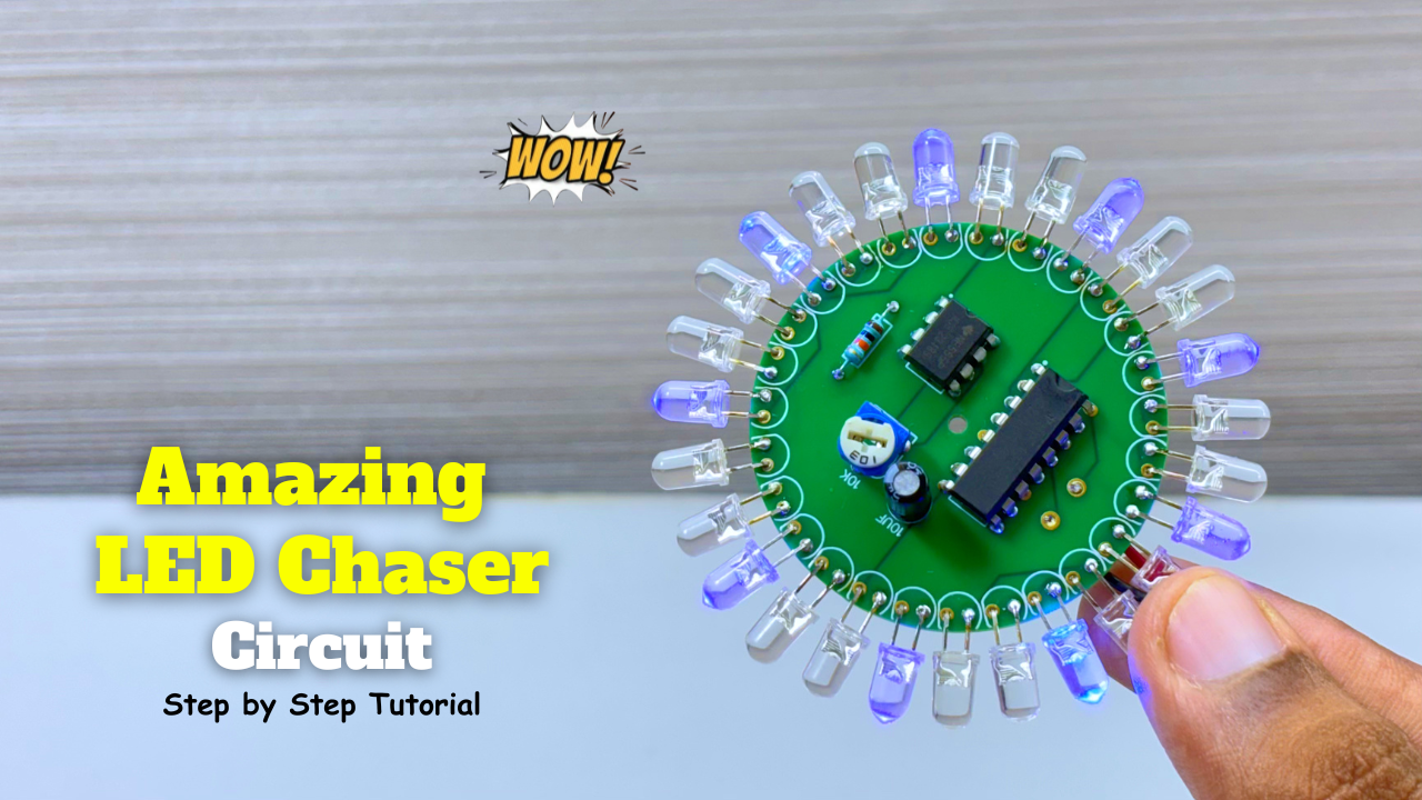
Amazing LED Chaser Circuit – Beautiful Decoration Idea
LED chasers are a fun and creative way to display a sequence of lights. In this blog post, we’ll show you how to build an LED chaser using a 555 …
-
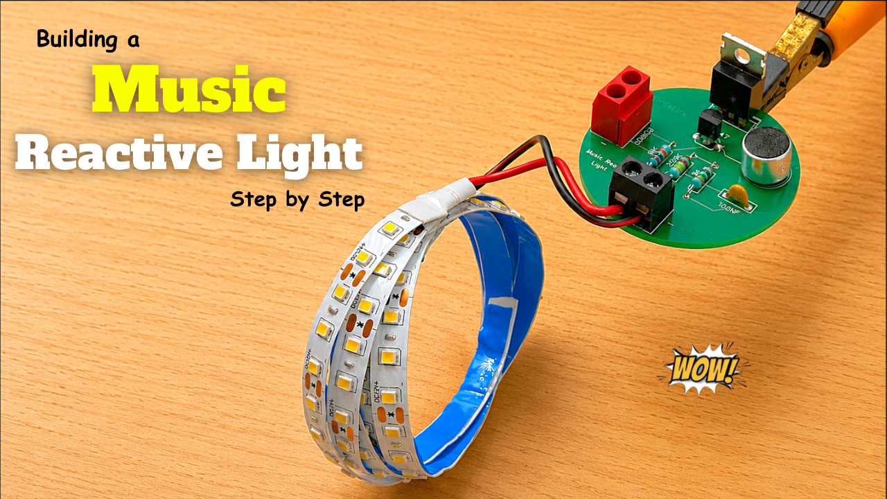
Music Reactive Light Circuit
A Music Reactive Light (also called a Sound Reactive Light or Music Sync Light) is a lighting system that changes its colors, brightness, or patterns according to the music or …
-
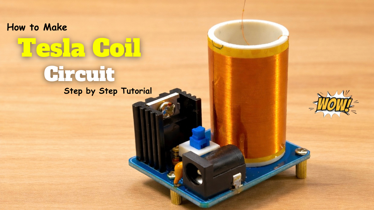
Mini Tesla Coil
A Tesla coil is an electrical device invented by Nikola Tesla in 1891. It is designed to generate very high voltage, low current, high-frequency electricity. In simple terms, it’s a …