An obstacle avoiding robot car is a robotic vehicle designed to navigate its environment without colliding with obstacles. It uses sensors and microcontrollers to detect and avoid obstacles in its path. These robots are commonly used in automation, robotics education, and as introductory projects for learning about electronics and programming.
Components
- Arduino Uno
- Ultrasonic Sensor (e.g., HC-SR04)
- Servo Motor
- Motor Driver Module (e.g., L298N)
- DC Motors
- Battery Pack
- Switch
- Arduino IDE
Working Principle
- Sensor Data Collection:
- The ultrasonic sensor continuously measures the distance between the robot and obstacles.
- Decision Making:
- The Arduino Uno processes sensor input.
- If the distance to an obstacle is below a threshold, the Arduino triggers a response (e.g., stop, turn left/right).
- Actuation:
- Based on the decision, the motor driver controls the DC motors to move the car forward, turn, or reverse.
Steps to Build an Obstacle Avoiding Robot Car
- Assemble the Hardware:
- Mount the motors, ultrasonic sensor, and Arduino on the chassis.
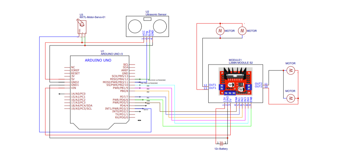
- Connect the components as per the circuit diagram.
- Write the Code:
- Write or upload the obstacle avoiding code to the Arduino using the Arduino IDE.
- Use libraries like
NewPingfor ultrasonic sensors if needed.
- Upload and Test:
- Upload the code to the Arduino Uno.
- Test the robot to ensure it detects and avoids obstacles correctly.
Circuit Diagram

Connections
| Component | Arduino Pin | Purpose |
|---|---|---|
| Servo Motor | Pin 3 | Controls servo rotation. |
| Ultrasonic Trigger | Pin 11 | Emits ultrasonic pulses. |
| Ultrasonic Echo | Pin 12 | Receives reflected pulses. |
| Right Motor Enable | Pin 5 | Controls speed (PWM). |
| Right Motor Dir 1 | Pin 7 | Sets direction (Forward/Reverse). |
| Right Motor Dir 2 | Pin 8 | Sets direction (Forward/Reverse). |
| Left Motor Enable | Pin 6 | Controls speed (PWM). |
| Left Motor Dir 1 | Pin 9 | Sets direction (Forward/Reverse). |
| Left Motor Dir 2 | Pin 10 | Sets direction (Forward/Reverse). |
Code
#include <Servo.h>
#include <NewPing.h>

#define SERVO_PIN 3
#define ULTRASONIC_SENSOR_TRIG 11
#define ULTRASONIC_SENSOR_ECHO 12
#define MAX_REGULAR_MOTOR_SPEED 60
#define MAX_MOTOR_ADJUST_SPEED 250
#define DISTANCE_TO_CHECK 30

// Right motor
int enableRightMotor = 5;
int rightMotorPin1 = 7;
int rightMotorPin2 = 8;

// Left motor
int enableLeftMotor = 6;
int leftMotorPin1 = 9;
int leftMotorPin2 = 10;

NewPing mySensor(ULTRASONIC_SENSOR_TRIG, ULTRASONIC_SENSOR_ECHO, 400);
Servo myServo;

void setup() {
  // Motor pin setup
  pinMode(enableRightMotor, OUTPUT);
  pinMode(rightMotorPin1, OUTPUT);
  pinMode(rightMotorPin2, OUTPUT);

  pinMode(enableLeftMotor, OUTPUT);
  pinMode(leftMotorPin1, OUTPUT);
  pinMode(leftMotorPin2, OUTPUT);

  // Servo setup
  myServo.attach(SERVO_PIN);
  myServo.write(90); // Center the servo initially
  rotateMotor(0, 0); // Stop motors initially
}

void loop() {
  int distance = mySensor.ping_cm();

  // If an object is detected within the threshold distance
  if (distance > 0 && distance < DISTANCE_TO_CHECK) {
    rotateMotor(0, 0);  // Stop motors
    delay(500);

    rotateMotor(-MAX_MOTOR_ADJUST_SPEED, -MAX_MOTOR_ADJUST_SPEED);  // Reverse
    delay(200);

    rotateMotor(0, 0);  // Stop motors
    delay(500);

    // Rotate the servo to the left and check the left side distance
    myServo.write(180);
    delay(500);
    int distanceLeft = mySensor.ping_cm();

    // Rotate the servo to the right and check the right side distance
    myServo.write(0);
    delay(500);
    int distanceRight = mySensor.ping_cm();

    // Return the servo to the center position
    myServo.write(90);
    delay(500);

    // Handle invalid distance readings (0 means no reading)
    if (distanceLeft == 0) distanceLeft = 999;  // Large value if no valid reading
    if (distanceRight == 0) distanceRight = 999;

    // Decide on which way to turn based on the side distances
    if (distanceLeft > distanceRight) {
      rotateMotor(MAX_MOTOR_ADJUST_SPEED, -MAX_MOTOR_ADJUST_SPEED);  // Turn left (more space on the left)
      delay(200);
    } else {
      rotateMotor(-MAX_MOTOR_ADJUST_SPEED, MAX_MOTOR_ADJUST_SPEED);  // Turn right (more space on the right)
      delay(200);
    }

    rotateMotor(0, 0);  // Stop motors
    delay(200);
  } else {
    // If no obstacle in front, move forward
    rotateMotor(MAX_REGULAR_MOTOR_SPEED, MAX_REGULAR_MOTOR_SPEED);
  }
}

// Function to control motor rotation based on speed
void rotateMotor(int rightMotorSpeed, int leftMotorSpeed) {
  // Right motor direction
  if (rightMotorSpeed < 0) {
    digitalWrite(rightMotorPin1, LOW);
    digitalWrite(rightMotorPin2, HIGH);
  } else {
    digitalWrite(rightMotorPin1, HIGH);
    digitalWrite(rightMotorPin2, LOW);
  }

  // Left motor direction
  if (leftMotorSpeed < 0) {
    digitalWrite(leftMotorPin1, LOW);
    digitalWrite(leftMotorPin2, HIGH);
  } else {
    digitalWrite(leftMotorPin1, HIGH);
    digitalWrite(leftMotorPin2, LOW);
  }

  // Set motor speeds
  analogWrite(enableRightMotor, abs(rightMotorSpeed));
  analogWrite(enableLeftMotor, abs(leftMotorSpeed));
}
Applications
- Automation:
- Useful in factories and warehouses for autonomous navigation.
- Education:
- A great project for learning robotics and Arduino programming.
- Hobbyist Projects:
- Popular among robotics enthusiasts for DIY projects.
- Research:
- Basis for advanced navigation and AI-based robots.
More Project
-
Building an Automatic Dark Sensor with BD139 Transistor
Light and darkness are two sides of the same coin, influencing our daily lives in ways we often overlook. Imagine a world where lights adjust themselves according to the ambient …
-
Safely Assembling 24V 100Ah Battery Pack – Step by Step!
Building an 8S (8 series) LiFePO4 battery pack using LiFePO4 cells and a Daly Battery Management System (BMS). If you’re planning your own DIY power storage project, this guide might …
-
How to Make 3.7v Li-ion Battery Charger
A 3.7 V lithium-ion charger using LM358 is a classic DIY solution and great for learning battery charging fundamentals. Below is a clear, practical explanation + working concept. Charging a …


