
Components Required :
- IN5408 Diode
- 12-0-12v 3A Transformer
- 4700uf 35v Capacitor
- Wire
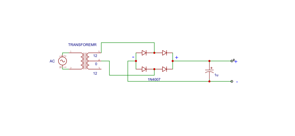
Circuit Diagram :
Electrical Transformer:
An electrical transformer is a static device that transfers electrical energy between two or more circuits through electromagnetic induction. It is a crucial component in power distribution systems and is used to step up or step down voltage levels, enabling the efficient transmission of electrical power over long distances.
Types of Transformers:
1. Step-Up Transformer:
– Increases the voltage from the primary winding to the secondary winding.
– Commonly used in power transmission to reduce energy losses during long-distance transmission.
2. Step-Down Transformer:
– Decreases the voltage from the primary winding to the secondary winding.
– Used in distribution systems to reduce the voltage to levels suitable for consumer use.
3. Isolation Transformer:
– Provides electrical isolation between the input and output windings, preventing direct connection between the two circuits.
– Used for safety and to suppress electrical noise.
4. Auto Transformer:
– Consists of a single winding with multiple taps.
– Can function as a step-up or step-down transformer depending on the tap selected.
Working Principle:
The basic working principle of a transformer relies on Faraday’s law of electromagnetic induction. When an alternating current (AC) flows through the primary winding, it creates a changing magnetic field around the winding. This changing magnetic field induces a voltage in the secondary winding through electromagnetic induction. The ratio of the number of turns in the primary and secondary windings determines the voltage transformation ratio.
Transformer Diagram:
A basic transformer consists of two coils (windings) wound on a common magnetic core. The primary winding is connected to the input voltage, and the secondary winding is connected to the output. The core is typically made of laminated iron or other magnetic materials.
Key Components:
1. Primary Winding: Connected to the input voltage source.
2. Secondary Winding: Connected to the output load.
3. Core: Provides a path for the magnetic flux and enhances the transformer’s efficiency.
Operation Steps:
1. AC current flows through the primary winding, creating a magnetic field in the core.
2. The changing magnetic field induces a voltage in the secondary winding.
3. The induced voltage in the secondary winding is transferred to the load connected to it.
Important Parameters:
1. Turns Ratio (N1/N2): The ratio of the number of turns in the primary winding (N1) to the number of turns in the secondary winding (N2).
2. Voltage Ratio (V1/V2): The ratio of the primary voltage (V1) to the secondary voltage (V2).
Transformers are fundamental in power distribution and are vital for ensuring efficient and safe electricity transmission. They play a crucial role in adjusting voltage levels to meet the requirements of different electrical devices and systems.
The 1N5408 is a type of rectifier diode. Here’s some information about the 1N5408 diode:
1N5408 Diode:
1. General Information:
– Type: Rectifier Diode
– Package: Axial leaded through-hole (DO-201AD)
– Voltage Rating (V_RRM): 1000 volts
– Forward Current (I_F): 3 amperes
– Reverse Recovery Time: Generally not specified or relatively slow compared to other diodes.
2. Purpose:
The 1N5408 diode is commonly used in power rectification applications. Rectifier diodes are essential in converting alternating current (AC) to direct current (DC) in power supply circuits, allowing the flow of current in one direction only.
3. Characteristics:
– Forward Voltage Drop (V_F): The forward voltage drop across the diode when it is conducting is typically around 0.7 volts.
– Reverse Leakage Current (I_R): The reverse leakage current is relatively low when the diode is in the reverse-biased state.
– Peak Surge Current: The diode can handle short-duration peak currents without getting damaged.
4. Applications:
– Power supply rectification circuits.
– Battery chargers.
– Power inverters.
– General-purpose rectification in electronic circuits.
5. Important Note:
– When using diodes in rectification circuits, it’s essential to consider the peak inverse voltage (PIV) or peak reverse voltage (PRV) that the diode will be subjected to. In the case of the 1N5408, it can handle a maximum reverse voltage of 1000 volts.
6. Pinout:
– The diode has two leads: the anode and the cathode.
– The cathode is typically marked with a band or a line on the body of the diode.
7. Alternatives:
– Other diodes in the 1N54xx series with different voltage and current ratings may be used depending on the specific requirements of the application.
When using any electronic component, it’s crucial to refer to the datasheet provided by the manufacturer for detailed specifications, electrical characteristics, and usage guidelines. The datasheet contains essential information for proper integration into a circuit.
Capacitor :
A capacitor is an electronic component that stores electrical energy in an electric field. It is a passive two-terminal device that consists of two conductive plates separated by an insulating material called the dielectric. Capacitors are widely used in electronic circuits for various purposes, including energy storage, filtering, coupling, and timing.
Key Characteristics of Capacitors:
1. Capacitance (C): Capacitance is the measure of a capacitor’s ability to store charge. It is measured in farads (F), but most capacitors are rated in microfarads (μF), nanofarads (nF), or picofarads (pF).
2. Voltage Rating: Capacitors have a maximum voltage they can withstand (voltage rating) before breakdown occurs. Exceeding this voltage can lead to the capacitor failing or even becoming damaged.
3. Dielectric Material: The dielectric material between the plates determines the capacitor’s characteristics. Common dielectric materials include ceramic, electrolytic (aluminum or tantalum), polyester, polypropylene, and others.
4. Polarity: Electrolytic capacitors are polarized and must be connected with the correct polarity. Non-polarized capacitors, such as ceramic and film capacitors, do not have a specific polarity.
5. Equivalent Series Resistance (ESR): ESR is the sum of all internal resistances within a capacitor. It affects the capacitor’s performance, especially in high-frequency applications.
6. Equivalent Series Inductance (ESL): ESL represents the inductive behavior of the capacitor. It becomes significant in high-frequency applications.
7. Temperature Coefficient: Capacitors can be sensitive to temperature changes. The temperature coefficient indicates how much the capacitance changes with temperature.
Types of Capacitors:
1. Ceramic Capacitors: These capacitors use a ceramic material as the dielectric. They are commonly used for bypass and decoupling applications.
2. Electrolytic Capacitors: These capacitors have an electrolyte as the dielectric and are polarized. Common types include aluminum electrolytic and tantalum capacitors.
3. Film Capacitors: Film capacitors use a thin plastic film as the dielectric. They come in various types, including polyester, polypropylene, and polycarbonate capacitors.
4. Variable Capacitors: These capacitors have an adjustable capacitance, allowing them to be tuned for specific applications, such as in radio frequency (RF) circuits.
5. Supercapacitors (Ultracapacitors): These capacitors have a much higher capacitance than traditional capacitors and are used for quick energy storage and release.
Applications:
– Energy Storage: Capacitors store energy and release it rapidly, making them suitable for applications requiring quick bursts of power.
– Filtering: Capacitors are used in filters to remove AC components and smooth DC voltage.
– Timing Circuits: Capacitors, in combination with resistors, are used in timing circuits to control the frequency of oscillators.
– Coupling: Capacitors couple AC signals while blocking DC, allowing the transmission of AC signals between stages in an amplifier
Capacitors play a crucial role in electronics, and their diverse types and characteristics make them versatile components in a wide range of applications.
-
Audio Level Indicator – VU Meter
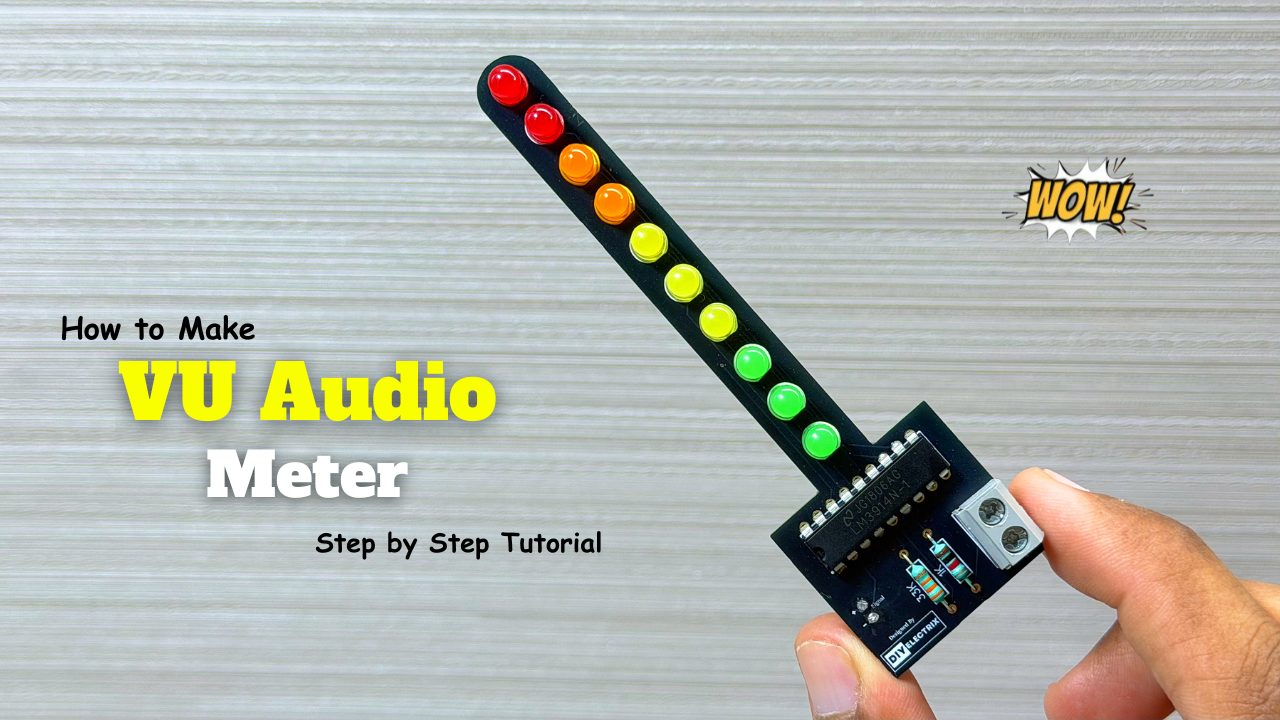
The VU meter—short for “volume unit meter”—is a device used to measure the average level of audio signals in terms of their loudness. It visually indicates the intensity of sound …
-
Powerful Audio Amplifier Using cd4440
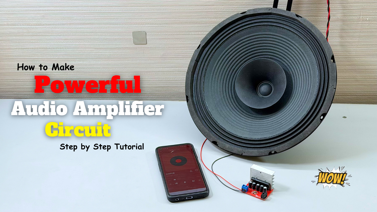
Welcome to our latest video where we delve into the fascinating world of audio amplification using the CD4440 IC! In this comprehensive guide, we’ll walk you through the step-by-step process …
-
Building an Automatic Dark Sensor with BD139 Transistor
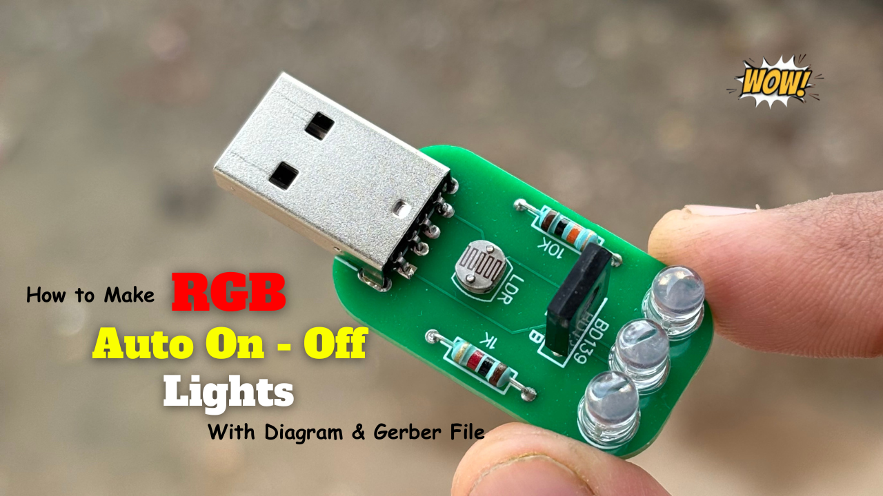
Light and darkness are two sides of the same coin, influencing our daily lives in ways we often overlook. Imagine a world where lights adjust themselves according to the ambient …